Turbocharger with external ball bearing

A turbocharger and ball bearing technology, which is applied to pump devices, non-variable capacity pumps, gas turbine devices, etc., can solve the problems of excessively long rotating shafts, high-speed noise sensitivity, inconvenient layout, etc., and achieve volume reduction. , Improve rigidity and avoid the effect of oil aging

Active Publication Date: 2020-09-11
宁波丰沃增压科技股份有限公司
View PDF8 Cites 1 Cited by
  • Summary
  • Abstract
  • Description
  • Claims
  • Application Information

AI Technical Summary

Problems solved by technology

[0005] The purpose of the present invention is to provide a ball bearing external turbocharger to solve the problem of large volume of the turbocharger proposed in the above background technology, inconvenient arrangement, too long shafting of the rotating shaft, complicated structure and low stiffness. High-speed noise-sensitive issues

Method used


Image

  • Turbocharger with external ball bearing
  • Turbocharger with external ball bearing
  • Turbocharger with external ball bearing

Examples


specific Embodiment 1

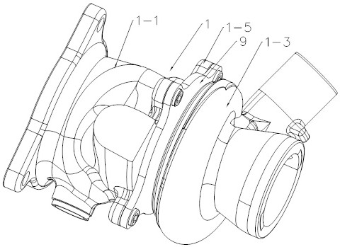
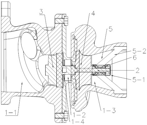
[0027] see Figure 1-4 , the present invention provides a technical solution: a ball bearing 6 external turbine 3 supercharger, including a body shell 1, a rotating shaft 2, a turbine 3 and an impeller 4, wherein the body shell 1 includes turbine chambers connected in sequence Body 1-1, intermediate cavity 1-2, compressed gas cavity 1-3, the turbine cavity 1-1, compressed gas cavity 1-3 are all provided with air inlets and gas outlets, and the turbine 3 is set A turbine is formed in the turbine cavity 1-1, and the impeller 4 is set in the compressor cavity 1-3 to form a compressor. The turbine 3 and the impeller 4 are both connected to the rotating shaft 2 to achieve coaxial linkage. In order to reduce the middle cavity The volume of the body 1-2 and the length of the rotating shaft 2 at the middle cavity 1-2, the support frame body 5 can be detachably connected to the compressed air cavity, and the rotating shaft 2 corresponds to the end of the compressed air cavity 1-3 It i...

specific Embodiment 2

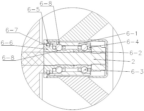
[0034] Such as Figure 5-7 As shown, on the basis of the specific embodiment 1, the outer ring 6-1 of the ball bearing 6 has an oil inlet hole 6-9 and an oil outlet hole respectively between the two rows of pocket ring surfaces 6-8. The oil hole 6-10, and the oil inlet hole 6-9 and the oil outlet hole 6-10 are all set corresponding to the supporting foot 5-2, and the shown supporting foot 5-2 has an oil passage communicated with the bearing outer casing 5-1 Channel 5-4, the oil channel 5-4 communicates with the oil inlet hole 6-9 and the oil outlet hole 6-10 respectively, and at the same time, the corresponding oil channel 5-4 on the connecting palm 5-3 has an oil port 5-5, the body shell 1 is provided with a valve corresponding to the oil port 5-5.

specific Embodiment 3

[0036] Such as Figure 8 As mentioned above, the difference between this specific embodiment and specific embodiment 1 or specific embodiment 2 is that the annular baffles 1-4 on both ends of the intermediate cavity 1-2 face the turbine cavity 1-1, the compressed air cavity 1-3 directions are embedded with sealing gaskets, and the inner ring baffle 1-6 is integrally provided around the rotating shaft 2 in the intermediate cavity 1-2 to form a sealed cavity, and the body shell 1 corresponds to the intermediate cavity 1 -2 has water inlet valve 7 and water outlet valve 8 respectively to form a closed water-cooled waterway, through which the adjacent turbine cavity 1-1 can be cooled to avoid heat conduction into the compressed air cavity 1-3.


PUM


Abstract

The invention discloses a turbocharger with an external ball bearing. According to the turbocharger, a ball bearing which supports the rotation of a rotating shaft is moved from an intermediate cavityto a compressed air cavity, and a support frame body fixed in the compressed air cavity and the ball bearing are matched to support the rotating shaft. The wheel distance between a turbine and a compressor in the turbocharger can be reduced, and the rigidity of the rotating shaft can be greatly improved, so that the trajectory of the rotating shaft and an axis is more stable when the rotating shaft rotates at high speed. The structure of the support frame body, the ball bearing and the rotating shaft can withstand a certain axial force and radial force without adding an additional thrust bearing design. The volume of the intermediate cavity can be greatly reduced, and the overall structure is simpler. Meanwhile, the ball bearing is placed outside the compressed air cavity to prevent the ball bearing from transmitting the high temperature in a turbine cavity, avoid the aging of the oil in the ball bearing, and prolong the service life.

Description

technical field [0001] The invention relates to the technical field of turbocharging equipment, in particular to a ball bearing external turbocharger. Background technique [0002] Turbocharging technology can greatly increase the power of piston engines, reduce exhaust pollution, and improve economic performance. It is one of the main development directions of internal combustion engine technology. [0003] The known turbocharger is equipped with a rotating shaft, a turbine and a compressor arranged at both ends of the rotating shaft, and the rotating shaft is rotatably supported by a bearing unit disposed between the compressor and the turbine, and the bearing unit is supplied with lubricating oil to form a deceleration. Vibrates the oil film to reduce wear caused by unwanted contact between components within the turbocharger. [0004] However, when the bearing unit is placed in the middle between the turbine and the compressor, the high temperature of the turbine will be...

Claims


Application Information

Patent Timeline
Patent Type & Authority Applications(China)
IPC IPC(8): F04D25/04F04D29/059F04D29/58F04D29/62F04D29/42F02C6/06F02B37/00
CPCF02B37/00F02C6/06F04D25/04F04D29/059F04D29/4206F04D29/5806F04D29/5853F04D29/624Y02T10/12
Inventor 闫文斌裴鹏军王永红王志华熊劲松
Owner 宁波丰沃增压科技股份有限公司
Why Eureka
Try Eureka