Drive axle cooling oil return filter device

A technology for oil filtration and driving axles, which is applied in the direction of fluid pressure actuation devices, fluid pressure actuation system components, mechanical equipment, etc. It can solve the problem of affecting the life of the brake mirror oil seal, easy adhesion on the surface of the filter element, and inconvenient inspection and replacement and other problems, to achieve the effect of reducing leakage points, improving filtration efficiency, and reducing oil return back pressure

Pending Publication Date: 2020-09-11
ANHUI HELI CO LTD
View PDF0 Cites 0 Cited by
  • Summary
  • Abstract
  • Description
  • Claims
  • Application Information

AI Technical Summary

Problems solved by technology

[0002] Existing heavy-duty port handling equipment, such as heavy-duty forklifts, empty container stackers, and container reach stackers, all use wet braking systems. The brakes on both sides of the drive axle need real-time heat dissipation and need to be set separately in the hydraulic system. The cooling system along the way ensures the real-time working temperature of the drive axle, and the abrasive particles generated by the brake spacers and friction plates also need to be intercepted in time, otherwise the abrasive particles will enter the hydraulic oil tank in large quantities and seriously affect the reliability of the system. Oil return filter, but currently the oil return filter assembly is arranged inside the car body, which is inconvenient to check and replace, and it is easy to increase the oil return leakage point; in addition, when the oil return filter is clogged, the bypass will be opened, which cannot Replacing the filter element in time greatly increases the risk of abrasive particles entering the hydraulic oil tank to contaminate the system; moreover, when the vehicle is first started at low temperature in winter, the residual hydraulic oil inside the oil return filter is relatively viscous and easily adheres to the surface of the filter element, increasing its The initial start-up back pressure, if the back pressure is greater than 1Bar for a long time, it will seriously affect the life of the brake mirror oil seal on both sides

Method used


Image

  • Drive axle cooling oil return filter device
  • Drive axle cooling oil return filter device
  • Drive axle cooling oil return filter device

Examples


Embodiment Construction

[0026] The following will clearly and completely describe the technical solutions in the embodiments of the present invention with reference to the accompanying drawings in the embodiments of the present invention. Obviously, the described embodiments are only some, not all, embodiments of the present invention. Based on the embodiments of the present invention, all other embodiments obtained by persons of ordinary skill in the art without making creative efforts belong to the protection scope of the present invention.

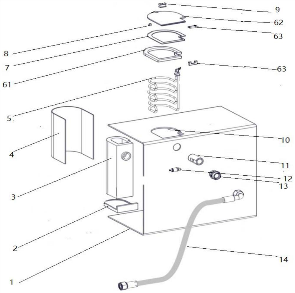
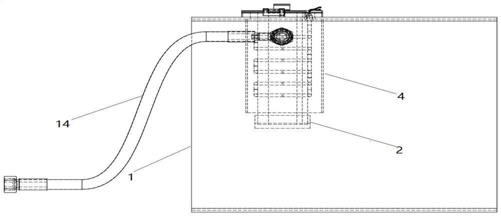
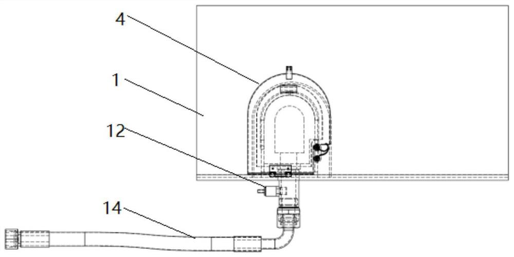
[0027] Attached below Figure 1-9 , the present invention will be further described by embodiment. In the embodiment of the present invention, a drive axle cooling oil return filter device includes a hydraulic oil tank box 1 and an oil return pipe 14 communicating with the box body 1 for guiding oil. The box body 1 has a built-in filter element 3 , the new structure filter element 3 is built inside the hydraulic oil tank body 1, which not only saves the filte...


PUM


Abstract

The invention discloses a drive axle cooling oil return filter device. The device comprises a box body of a hydraulic oil tank and an oil return pipe communicated with the box body and used for guiding oil, a filter element is arranged in the box body, the inner wall of the box body is fixedly connected with a backing plate, the filter element is fixedly connected on the backing plate, and an oiloutlet of the oil return pipe is communicated with an inner cavity of the filter element. A new structure filter element in the device is of a double-layer structure, through an annular flow channel formed between the inner and outer filter element layers, the filter area is increased, the filtration efficiency is improved, when the annular flow channel cooperates with low temperature heating, oilaccumulation is effectively reduced, and a small oil return back pressure is formed; in addition, the filter element is built into the hydraulic oil tank, so that a filter of a traditional brake oilreturn belt housing is eliminated, and leakage points are reduced.

Description

technical field [0001] The invention relates to the technical field of replacing the filter inner core of a drive axle, in particular to a filter device for cooling and returning oil of a drive axle. Background technique [0002] Existing heavy-duty port handling equipment, such as heavy-duty forklifts, empty container stackers, and container reach stackers, all use wet braking systems. The brakes on both sides of the drive axle need real-time heat dissipation and need to be set separately in the hydraulic system. The cooling system along the way ensures the real-time working temperature of the drive axle, and the abrasive particles produced by the brake spacers and friction plates also need to be intercepted in time, otherwise the abrasive particles will enter the hydraulic oil tank in large quantities and seriously affect the reliability of the system. Oil return filter, but currently the oil return filter assembly is arranged inside the car body, which is inconvenient to ...

Claims


Application Information

Patent Timeline
Patent Type & Authority Applications(China)
IPC IPC(8): F15B21/041F15B21/0427
CPCF15B21/041F15B21/0427
Inventor 毕胜杨雪松吴猛刘敏杨书强
Owner ANHUI HELI CO LTD
Why Eureka
Try Eureka