Pneumatic impact table

An impact table and pneumatic technology, which is applied in the field of pneumatic impact table, can solve the problems of increasing the cost of guide columns, requiring high installation space, and high columns, and achieves the effects of compact structure, reliable braking method, and high impact speed

Active Publication Date: 2020-09-11
SUZHOU DONGLING VIBRATION TEST INSTR
View PDF16 Cites 0 Cited by
  • Summary
  • Abstract
  • Description
  • Claims
  • Application Information

AI Technical Summary

Problems solved by technology

This will lead to a very high guide column, increase the cost of the guide column, and require a high installation space

Method used


Image

  • Pneumatic impact table
  • Pneumatic impact table
  • Pneumatic impact table

Examples


Embodiment Construction

[0031] The present invention will be further described below in conjunction with the accompanying drawings and specific embodiments, so that those skilled in the art can better understand the present invention and implement it, but the examples given are not intended to limit the present invention.

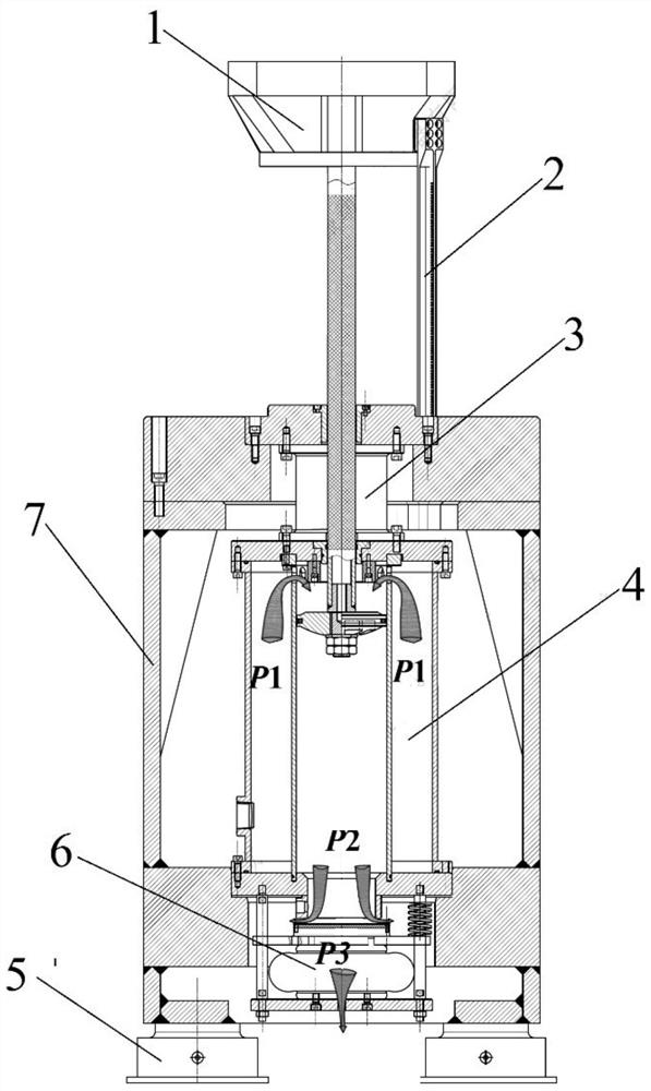
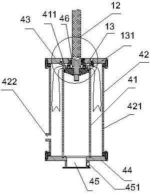
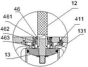
[0032] Such as figure 1 As shown, the present invention provides a pneumatic impact table. The impact table includes a table assembly 1 , an impact cylinder assembly 4 , and a housing 7 . The impact cylinder assembly 4 is installed in the housing 7 . Such as figure 2 and 3As shown, the impact cylinder assembly 4 includes an outer cylinder 42, an inner cylinder 41 located in the outer cylinder 42, an upper cover 43 of the impact cylinder, a lower cover 44 of the impact cylinder, the outer cylinder 42 and the inner cylinder 41 is sealed by the impact cylinder upper cover 43, the outer cylinder 42 and the lower end of the inner cylinder 41 are sealed by the impact cylinder lower c...


PUM


Abstract

The invention provides a pneumatic impact table. The pneumatic impact table comprises a table board assembly, an impact cylinder assembly and a shell, wherein the impact cylinder assembly is arrangedin the shell; the impact cylinder assembly comprises an outer cylinder, an inner cylinder arranged in the outer cylinder, an upper impact cylinder cover and a lower impact cylinder cover. The upper end parts of the outer cylinder and the inner cylinder are sealed through the upper impact cylinder cover; the lower end parts of the outer cylinder and the inner cylinder are sealed through the lower impact cylinder cover; the table board assembly comprises a working table board, a piston rod connected to the lower portion of the working table board, and a piston head connected to the lower end ofthe piston rod. The piston rod penetrates through the upper impact cylinder cover; the piston head is arranged in the inner cylinder in an up-down moving mode, an inner cavity of the inner cylinder isdivided into an inner cavity upper portion located on the upper side of the piston head and an inner cavity lower portion located on the lower side of the piston head by the piston head, and a plurality of vent holes are formed in the side wall of the upper end of the inner cylinder.

Description

technical field [0001] The invention relates to the impact test of the mechanical environment test technology, in particular to a pneumatic impact table. Background technique [0002] The impact table test equipment is mainly used in the mechanical environment test of the product. By simulating the impact environment that the product may suffer during use, loading and unloading and transportation, the functional reliability and structural integrity of the product under this impact environment are assessed. [0003] Conventional vertical impact test equipment mainly adopts the method of free fall. Its working principle is that the test piece is installed on a table, and a certain lifting mechanism is used to lift the work table to a certain height, and then release the table, so that the table and the test piece fall freely together. Go to the chopping board where the waveform generator is installed to generate the desired shock waveform. From the time when the platform fall...

Claims


Application Information

Patent Timeline
Patent Type & Authority Applications(China)
IPC IPC(8): G01M7/08
CPCG01M7/08
Inventor 仝宁可胥小强陈婷
Owner SUZHOU DONGLING VIBRATION TEST INSTR
Why Eureka
Try Eureka