Test equipment for MA modular bridge expansion device and test method thereof

A technology of expansion devices and test equipment, which is applied in bridge construction, bridges, bridge parts, etc., can solve the problems of lack of detection equipment and detection methods for MA modular bridge expansion devices

Pending Publication Date: 2020-09-11
甘肃省公路工程质量试验检测中心有限公司
View PDF0 Cites 0 Cited by
  • Summary
  • Abstract
  • Description
  • Claims
  • Application Information

AI Technical Summary

Problems solved by technology

[0009] The object of the present invention is to provide a kind of test equipment and test method thereof for MA modular bridge expansion device, to solve the problem that the MA modular bridge expansion device lacks relevant detection equipment and detection methods

Method used


Image

  • Test equipment for MA modular bridge expansion device and test method thereof
  • Test equipment for MA modular bridge expansion device and test method thereof
  • Test equipment for MA modular bridge expansion device and test method thereof

Examples


Embodiment 1

[0113] A test method for the test equipment of the MA modular bridge expansion device--the test method for the qualified judgment of the section size, the qualified judgment of the designed expansion and contraction, and the qualified judgment of the clamping performance of the rubber sealing tape:

[0114] Step 1. Judgment of the qualified cross-sectional size of the sample:

[0115] Place the MA modular bridge expansion device (hereinafter referred to as the sample) in the test room at 23°C ± 5°C for no less than 24 hours. There should be no corrosive gas and vibration sources that affect the detection in the test room.

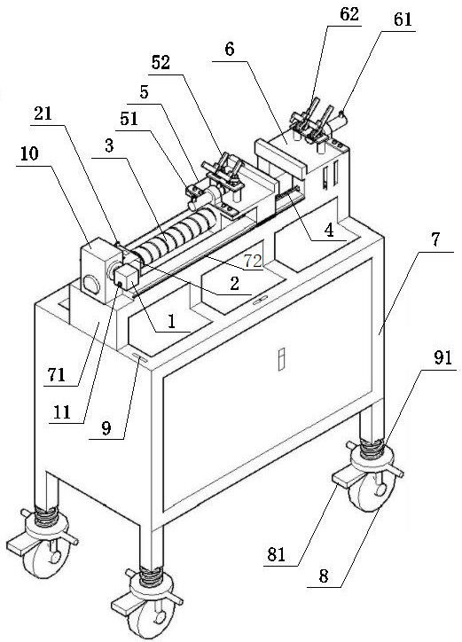
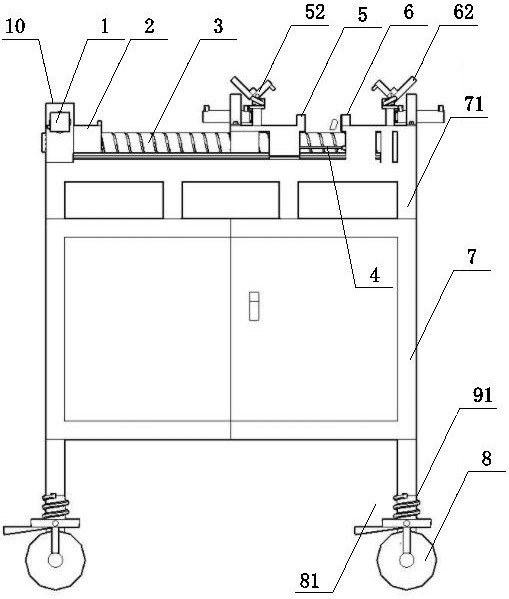
[0116] Move the two sets of equipment of the present invention to the designated test position through the moving wheel 8 and fix the equipment of the present invention by means of the limiter 81, and use the cooperation of the level gauge 9 and the leveling device 91 to level the equipment of the present invention.

[0117] By adjusting the position of the...

Embodiment 2

[0165] A test method for the test equipment of the MA modular bridge expansion device-vertical misalignment test method:

[0166] The difference between this embodiment and embodiment 1 lies in the following content:

[0167] In this test, the height of the sample side beam fixed at the front end of the test device of the present invention is kept constant, and the test is carried out by adjusting the height of the sample side beam pad of the test device at the rear end, simulating the situation that the vertical dislocation of the bridge in the expansion joint occurs in reality .

[0168] When step 2 test is qualified in embodiment 1, change over to following test procedure:

[0169] Step B: Vertical misalignment test:

[0170] The test conditions are the same as in Example 1.

[0171] 1. The sample is fixed.

[0172] Before the sample is fixed in step 2, the edge beam of the front-end sample is raised with pads, specifically: the pads whose length and width correspond to...


PUM


Abstract

The invention discloses test equipment for an MA modular bridge expansion device and a test method of the test equipment, belongs to the technical field of road and bridge detection, and aims to solvethe problem that the MA modular bridge expansion device lacks related detection equipment and detection methods. The test equipment comprises loading equipment and sample fixing equipment, the loading equipment comprises a motor and a traction rod which are connected with each other; the sample fixing equipment comprises a movable pedestal and a fixed pedestal which are symmetrically arranged. The method comprises the steps of judging whether the section size is qualified or not, judging whether the designed expansion amount is qualified or not and judging whether the rubber sealing tape clamping performance is qualified or not, and a vertical dislocation test method is performed; the test equipment makes up the blank of the current MA modular bridge expansion device and related test detection methods on the whole, forms perfect special test equipment and method for the MA modular bridge expansion device through equipment research and development, matching methods and judgment standards, and has important popularization significance.

Description

technical field [0001] The invention belongs to the technical field of road and bridge detection, and in particular relates to a test device and a test method for an MA modulus bridge expansion device. Background technique [0002] The current standard JT / T327-2016 "General Technical Conditions for Highway Bridge Expansion Devices" of the transportation industry defines the deformation performance, maximum horizontal friction resistance, maximum vertical deformation deviation per unit, misalignment performance, and bearing capacity limit of MB modular bridge expansion devices. The test methods and some performance requirements are given for routine items such as state checking, bearing performance, and rubber sealing belt clamping performance, but there are no requirements for the test methods and performance of the MA modular bridge expansion device. [0003] MA modular bridge expansion devices are widely used in the northwestern provinces of my country, but the relevant te...

Claims


Application Information

Patent Timeline
Patent Type & Authority Applications(China)
IPC IPC(8): G01M13/00E01D19/06
CPCE01D19/06G01M13/00
Inventor 马蔚付涛梁彦和范善智
Owner 甘肃省公路工程质量试验检测中心有限公司
Why Eureka
Try Eureka