Beam position detector mechanical center calibration method based on longitudinal phase measurement

A beam position and calibration method technology, applied in measurement devices, radiation measurement, X/γ/cosmic radiation measurement, etc., can solve the problem that the accelerator cannot accurately calibrate the mechanical center of the beam position detector.

Active Publication Date: 2020-09-11
SHANGHAI INST OF APPLIED PHYSICS - CHINESE ACAD OF SCI +1
View PDF5 Cites 0 Cited by
  • Summary
  • Abstract
  • Description
  • Claims
  • Application Information

AI Technical Summary

Problems solved by technology

[0005] In order to solve the problem in the prior art that the accelerator cannot accurately calibrate the mechanical center of the beam position detector during operation, the present invention provides a method for calibrating the mechanical center of the beam position detector based on the longitudinal phase relationship

Method used


Image

  • Beam position detector mechanical center calibration method based on longitudinal phase measurement
  • Beam position detector mechanical center calibration method based on longitudinal phase measurement
  • Beam position detector mechanical center calibration method based on longitudinal phase measurement

Examples


Embodiment Construction

[0033] Below in conjunction with the drawings, preferred embodiments of the present invention are given and described in detail.

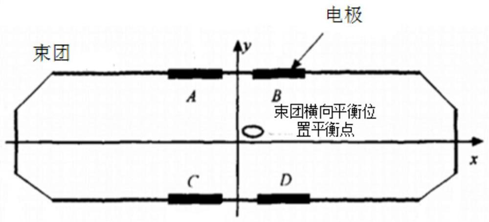
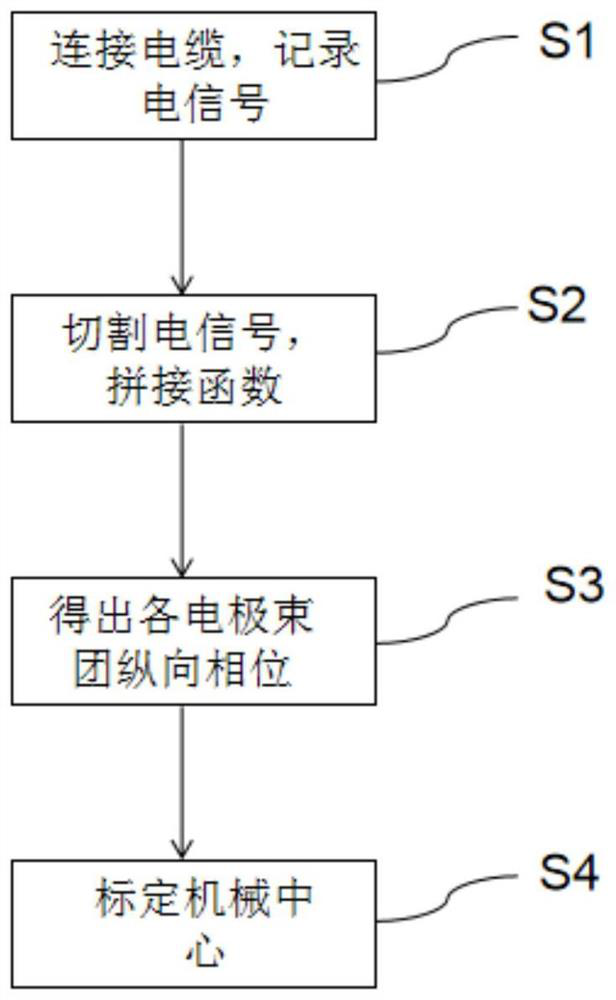
[0034] The beam position detector mechanical center calibration method based on the longitudinal phase provided by the present invention, such as figure 2 shown, including the following steps:

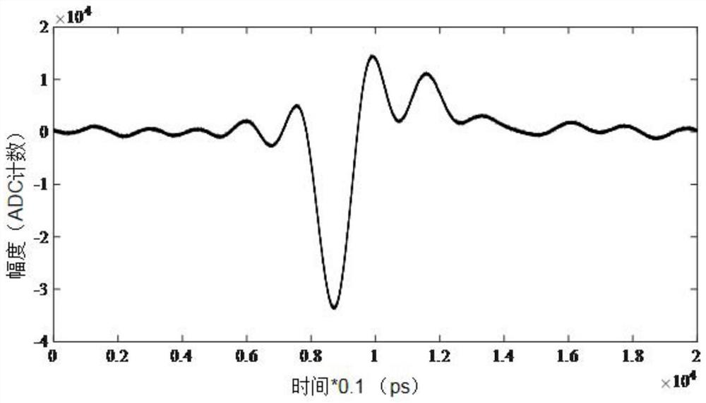
[0035] Step S1, connect four cables with the same delay time to four different electrode probes of the beam position detector respectively, and connect the other end to the measuring end of the oscilloscope, and record the electrical signals of the four electrodes at the same time. Among them, the purpose of the same delay time of each cable is to eliminate the source of the phase difference and ensure the same propagation time of the signal to the receiving end. In addition, considering the short period of the bunch, it is necessary to use an oscilloscope with a sampling rate higher than 10 GHz to collect enough sampling points when a bunch passes. In t...


PUM

PropertyMeasurementUnit
Sampling rateaaaaaaaaaa

Abstract

The invention relates to a beam position detector mechanical center calibration method based on a longitudinal phase relation, and the method comprises the steps: firstly enabling a cable to be connected to different electrode probes of a beam position detector, enabling the cable to be connected to a measurement end of an oscilloscope, and recording an electric signal of each electrode; secondly,cutting the electric signal of each electrode according to the interval time T to obtain a plurality of single-beam cluster signals, and splicing corresponding functions of the electrode signals; measuring a beam bunch longitudinal phase corresponding to each electrode signal according to a corresponding function of the electrode signal; and finally, judging whether the beam bunch longitudinal phases corresponding to the electrode signals are equal or not, and completing calibration of the mechanical center. According to the invention, the mechanical center of the beam position detector can be accurately calibrated under the condition that the beam position detector is already installed on the accelerator and the accelerator operates normally, and the operation state of the beam is not influenced. In addition, the differential loss of the intermediate element can be further measured by fully utilizing the mechanical center.

Description

technical field [0001] The invention relates to particle accelerator physical beam current diagnosis technology and instrument state analysis, and more particularly relates to a beam position detector mechanical center calibration method based on longitudinal phase relationship. Background technique [0002] The four-electrode beam position detector (BPM) is widely used in the beam position detection of storage ring accelerators, such as figure 1 As shown, the four electrodes are symmetrically distributed on the vacuum wall, and the beam current position is usually obtained by performing a difference ratio sum operation on the voltage values ​​of the four electrodes. [0003] The mechanical center of the four-electrode beam position detector refers to the midpoint of two symmetrical electrodes, that is, the mechanical center in a certain direction is the same distance from the center of the two electrodes in this direction. The confirmation of the mechanical center has a gr...

Claims


Application Information

Patent Timeline
IPC IPC(8): G01T1/29
CPCG01T1/29
Inventor 许兴懿冷用斌周逸媚
Owner SHANGHAI INST OF APPLIED PHYSICS - CHINESE ACAD OF SCI
Why Eureka
Try Eureka