Micro-channel heat dissipation system and manufacturing method thereof

A technology of a heat dissipation system and a manufacturing method, which is applied in the manufacture of semiconductor/solid state devices, semiconductor/solid state device components, semiconductor devices, etc., can solve the problems of good heat dissipation effect of microchannels and simple manufacturing process, and solve the problem of chip heat dissipation , low cost, good heat dissipation effect

Inactive Publication Date: 2020-09-11
SHANGHAI XIANFANG SEMICON CO LTD +1
View PDF8 Cites 14 Cited by
  • Summary
  • Abstract
  • Description
  • Claims
  • Application Information

AI Technical Summary

Problems solved by technology

[0005] The purpose of the present invention is to provide a micro-channel heat dissipation system and its manufacturing method to solve the problem that the existing micro-channel heat dissipation cannot achieve good heat dissipation effect and simple manufacturing process at the same time

Method used


Image

  • Micro-channel heat dissipation system and manufacturing method thereof
  • Micro-channel heat dissipation system and manufacturing method thereof
  • Micro-channel heat dissipation system and manufacturing method thereof

Examples


Embodiment 1

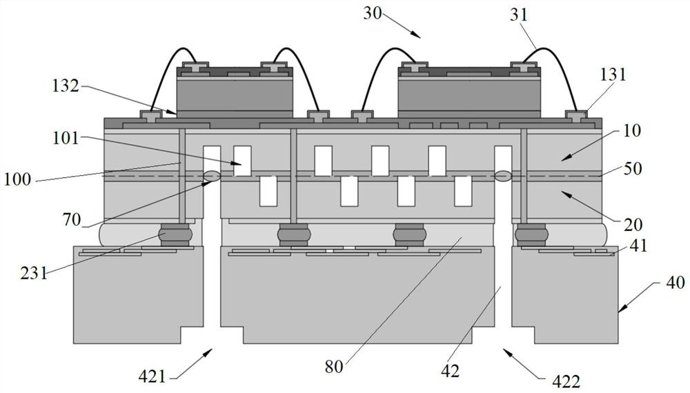
[0065] This embodiment provides a microchannel cooling system, such as figure 1 As shown, the microfluidic heat dissipation system includes sequentially stacked active chips 30, passive components (such as the first passive component 10 and the second passive component 20) and signal interconnection board 40, wherein: the passive The source device includes a first signal interconnection system 100 and a first microchannel heat dissipation system 101; the signal interconnection board 40 includes a second signal interconnection system 41 and a second microchannel heat dissipation system 42; the active The chip 30 has a third signal interconnection system 31; the third signal interconnection system 31, the first signal interconnection system 100 and the second signal interconnection system 41 are electrically connected in sequence; the first microflow The channel cooling system 101 communicates with the second micro-channel cooling system 42 to form a channel for cooling fluid. ...

Embodiment 2

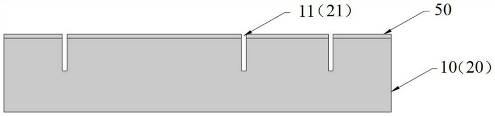
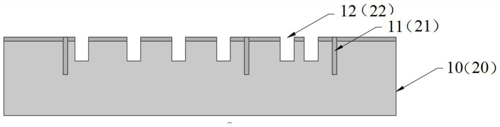
[0072] This embodiment provides a method for manufacturing a microfluidic cooling system, such as Figure 2-12 As shown, the manufacturing method of the micro-channel heat dissipation system includes: forming a first signal interconnection system 100 and a first micro-channel heat dissipation system 101 on at least one passive device; forming a second signal interconnection system 101 on a signal interconnection board 40 Signal interconnection system 41; make the first signal interconnection system 100 electrically connected to the second signal interconnection system 41; connect at least one active chip 30 to the passive device, and the active chip 30 has a third signal interconnection system 31, so that the first signal interconnection system 100 is electrically connected to the third signal interconnection system 31; a second micro-channel cooling system 42 is formed on the signal interconnection board 40; The first micro-channel cooling system 101 communicates with the sec...


PUM


Abstract

The invention provides a micro-channel heat dissipation system and a manufacturing method thereof. The manufacturing method of the micro-channel heat dissipation system comprises the following steps:forming a first signal interconnection system and a first micro-channel heat dissipation system on at least one passive device; forming a second signal interconnection system on a signal interconnection board; electrically connecting the first signal interconnection system with the second signal interconnection system; connecting at least one active chip to the passive device, enabling the activechip to be provided with a third signal interconnection system, and enabling the first signal interconnection system to electrically connected with the third signal interconnection system; forming a second micro-channel heat dissipation system on the signal interconnection plate; and communicating the first micro-channel heat dissipation system with the second micro-channel heat dissipation systemto form a heat dissipation fluid passage.

Description

technical field [0001] The invention relates to the technical field of semiconductor devices, in particular to a microfluidic cooling system and a manufacturing method thereof. Background technique [0002] With the continuous reduction of chip size, the continuous improvement of chip integration, more and more powerful functions, and higher and higher packaging densities. As a result, the power consumption per unit volume of the chip increases sharply, and the temperature of the chip rises sharply, resulting in reduced reliability of the chip and affecting normal operation of the chip. The study found that the system reliability will be reduced by half for every 10°C increase in the temperature of the active components. At the same time, the failure of more than 55% of electronic equipment is caused by excessive temperature. It can be seen that the heat dissipation problem of chips has become a key element in the normal operation of electronic equipment. Microchannel hea...

Claims


Application Information

Patent Timeline
Patent Type & Authority Applications(China)
IPC IPC(8): H01L21/48H01L21/768H01L23/367H01L23/473H01L23/48
CPCH01L23/473H01L23/3677H01L23/481H01L21/4882H01L21/76898H01L2224/32225H01L2224/73265H01L2224/48227H01L2224/48091H01L2924/00014H01L2924/00
Inventor 张鹏曹立强樊嘉祺
Owner SHANGHAI XIANFANG SEMICON CO LTD
Why Eureka
Try Eureka