
Shielding tail cover

A technology of tail cover and tail clamp, which is applied in the direction of electrical components, coupling devices, circuits, etc., can solve the problems of shielding performance impact, cable damage, cable damage, etc., to improve shielding efficiency, buffer alternating stress, and good shielding effect Effect

Pending Publication Date: 2020-09-11
SUZHOU HUAZHAN SPACE APPLIANCE
View PDF0 Cites 0 Cited by
  • Summary
  • Abstract
  • Description
  • Claims
  • Application Information

AI Technical Summary

Problems solved by technology

In the process of applying the above technology, the termination technology of the cable and the shielding layer and the connector tail end has not been well resolved. In the equipment of the prior art, the shielded connector is used to match the shielded cable, and the cable shielding layer adopts a common tail. The existing problem is that not only the wire clamp cannot achieve good grounding, but also the clamping force of the cable shielding layer is not enough, the shielding layer comes out, the shielding performance is affected, and it cannot solve the problem of multiple cables uniformly shielding the outside ; There is also a copper net on the shielding layer to clamp the cable with the clamp. The problem is that the cable connected by this connection method will not only be clamped by the clamp, but the clamping force will be directly pressed to the shielding layer through the copper net. , and then pressed to the cable under the shielding layer, causing the cable to be damaged, and the cable clamping force cannot be controlled. If it is loose, it is easy to cause the cable to come out. If it is tight, it is inevitable that the long external cable of the device will be dragged and trampled during use. , this phenomenon causes the cable to produce bending alternating stress at the end of the connector, which makes the phenomenon of cable damage and root fracture more and more serious, especially for high-speed and high-frequency applications, which seriously affects its high-speed and high-frequency performance, resulting in its function failure

Method used


Image

  • Shielding tail cover
  • Shielding tail cover
  • Shielding tail cover

Examples


Embodiment 1

[0032] The present invention is used to connect the shielding layer of the cable itself:

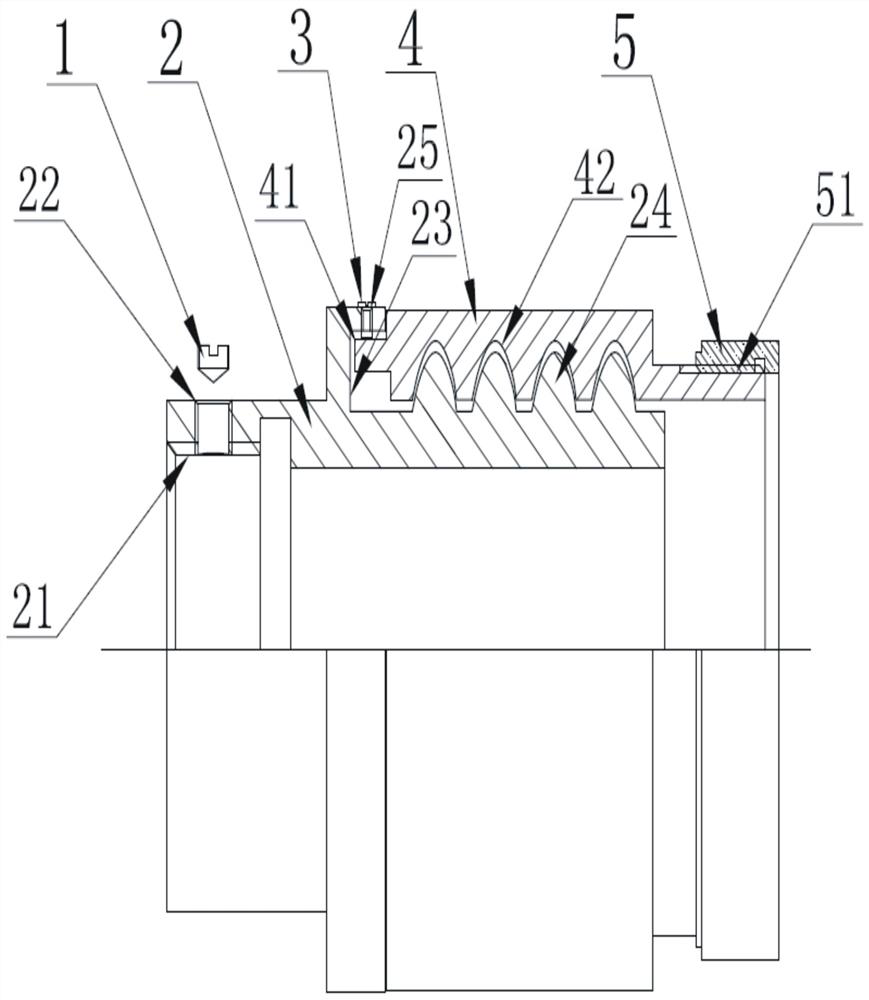
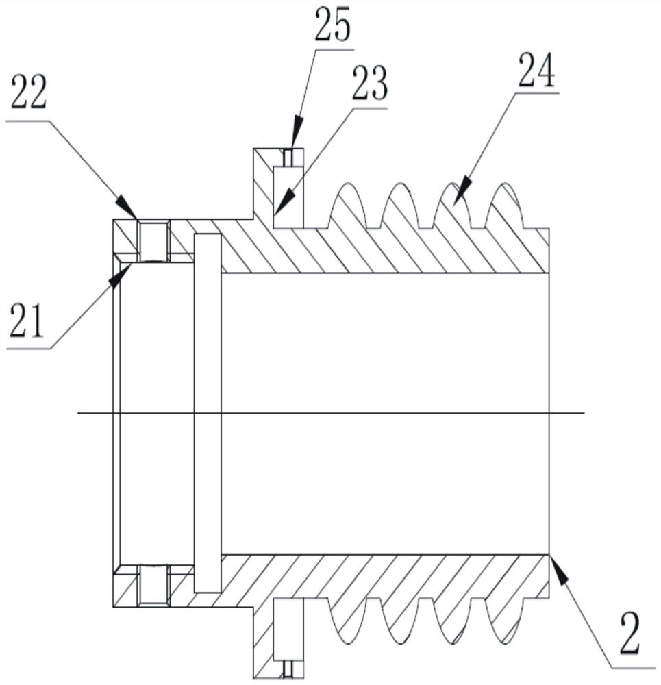
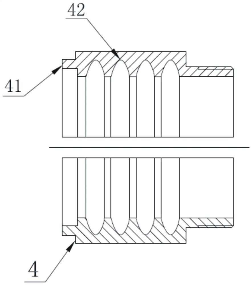
[0033] refer to figure 1 , Figure 5 , for the connection of a single cable with its own shielding layer, the core, shielding layer and insulation layer of the cable are stripped; the screw sleeve 5 and the tail cover shell 2 are inserted into the cable in sequence, and the core of the cable and the connector Connect the terminal of the terminal, put the shielding layer of the cable on the surface of the corrugated surface 24 protruding from the tail cover shell 2, fasten the tail clip 4 on the tail cover shell 2, and install the boss 41 of the tail clip 4 on the tail cover shell 2. In the notch 23 of the cover shell 2, as the concave corrugations 42 on the tail clip 4 engage with the convex corrugations 24 on the tail cover shell 2, the shielding layer is squeezed between the tail cover shell 2 and the tail clip 4 Between them, the internal thread 51 of the threaded sleeve 5 is engage...

Embodiment 2

[0036] The present invention is used to connect the additional shielding layer of the cable:

[0037] refer to figure 1 , Figure 6 , for multiple cables, no matter whether the cables have their own shielding layer or not, the multiple cables need to be uniformly shielded externally. At this time, the additional shielding layer 6 of the sleeve shape is used; one end of the additional shielding layer 6 is connected to the present invention, through the present invention The invention is connected with a connector, and the other end is connected with the outer surfaces of multiple cables by binding them with clamps.

[0038] When connecting, first strip the wire cores, shielding layers and insulating layers of multiple cables; put the additional shielding layer 6, screw sleeve 5 and tail cover shell 2 into multiple cables in sequence, and connect the cores of multiple cables with each other in sequence. Connect the connecting terminal of the connector, put the additional shiel...

Embodiment 3

[0041] To place a cable and additional shielding between two pieces of the invention:

[0042] refer to figure 1 , Figure 7 , one end of the additional shielding layer 6 is connected to the present invention, connected to a connector through the present invention, and the other end is connected to another connector through the present invention; the additional shielding layer 6 is arranged between the two present inventions, and the cable The received external force is transmitted to the two tail cover shells 2 through the shielding layer, and then respectively transmitted to the two connectors by the two tail cover shells 2, so as to slow down and eliminate the stress on the connection point between the cable and the terminal.

[0043] refer tofigure 1 The stepped hole 21 of the tail cover housing 2 of the present invention is adapted to the end of the connector, which can be used for circular or rectangular connectors to realize the processing of a single cable or multiple...


PUM


Abstract

The invention discloses a shielding tail cover. The shielding tail cover comprises a bolt, a tail cover shell, a set screw, a tail clamp and a threaded sleeve. The structure of the tail cover shell, the tail clamp and the threaded sleeve is adopted; the shielding tail cover can be used for connecting a shielding layer of a cable, and can also be used for connecting an additional shielding layer ofthe cable. The shielding layer is fixedly connected through a corrugated surface by adopting the tail cover shell and the tail clamp, so the problem of unified external shielding of a plurality of cables is solved; and the tail cover shell is fixedly connected with the tail end of a connector, so external force borne by the cable is transmitted to the tail cover shell through the shielding layerand then transmitted to the connector through the tail cover shell, stress of a connection point of the cable and the terminal is relieved and eliminated, alternating stress borne by the cable at thetail end of the connector is buffered. The shielding tail cover has the advantages of being simple in structure, convenient to use, reliable in connection and good in shielding effect.

Description

technical field [0001] The invention relates to the technical field of shielding of electrical connectors, a shielding cover for preventing electromagnetic radiation or electromagnetic interference, in particular to a shielding tail cover. Background technique [0002] With the rapid development of electronic equipment, in order to solve the shielding problem of electronic equipment, a variety of technical means have emerged, such as the application of electronic jammers, the application of shielding grounding technology for connector docking, and the application of cable shielding sheath technology. In the process of applying the above technology, the termination technology of the cable and the shielding layer and the connector tail end has not been well resolved. In the equipment of the prior art, the shielded connector is used to match the shielded cable, and the cable shielding layer adopts a common tail. The existing problem is that not only the wire clamp cannot achiev...

Claims


Application Information

Patent Timeline
IPC IPC(8): H01R13/6581H01R13/6585
CPCH01R13/6581H01R13/6585
Inventor 陈银桂杜建东沈斌孔晓峰
Owner SUZHOU HUAZHAN SPACE APPLIANCE
Learn More