Wind turbine and its fan shaft

A technology for wind turbines and main shafts, which is applied in the direction of wind power generators, wind power generation, engines, etc., and can solve the problems of increased size, low production efficiency and high production cost of wind turbine main shafts

Inactive Publication Date: 2017-08-22
STATE GRID CORP OF CHINA +2
View PDF4 Cites 0 Cited by
  • Summary
  • Abstract
  • Description
  • Claims
  • Application Information

AI Technical Summary

Problems solved by technology

At present, the diameter of the wind turbines of the MW-level wind turbines in the breeze area and the wind turbines of 3MW and above are getting bigger and bigger, and the weight is also increasing, which causes the size of the connecting flange adjacent to the fan hub on the fan shaft to increase. The shaft diameter of the main shaft of the wind turbine is also increased accordingly; in addition, as people pay more and more attention to the local Hertz contact stress of the main shaft bearing, the main shaft bearing of the wind turbine tends to choose a multi-row single bearing with a larger inner diameter. The bearing installation ring platform for fan bearing installation is provided, so that the diameter of the connecting flange and the bearing installation ring platform of the fan main shaft is relatively large, and the diameter between the connecting flange and the bearing installation ring platform and on both sides is small Complex structures such as figure 1 As shown, item 1 in the figure represents the main shaft body, item 2 represents the connecting flange for realizing the connection of the fan hub, and item 3 represents the bearing installation ring platform for realizing the installation of the main shaft bearing. In order to ensure the structural strength of the main shaft, the main shaft body, the connecting flange and The bearing mounting ring is integrally formed by alloy steel. For such a complex fan main shaft structure similar to the engine crankshaft, it is difficult to use the crankshaft forging process. There are many problems, which will lead to low production efficiency and high production cost of such a large-structure fan shaft

Method used


Image

  • Wind turbine and its fan shaft
  • Wind turbine and its fan shaft
  • Wind turbine and its fan shaft

Examples


Embodiment Construction

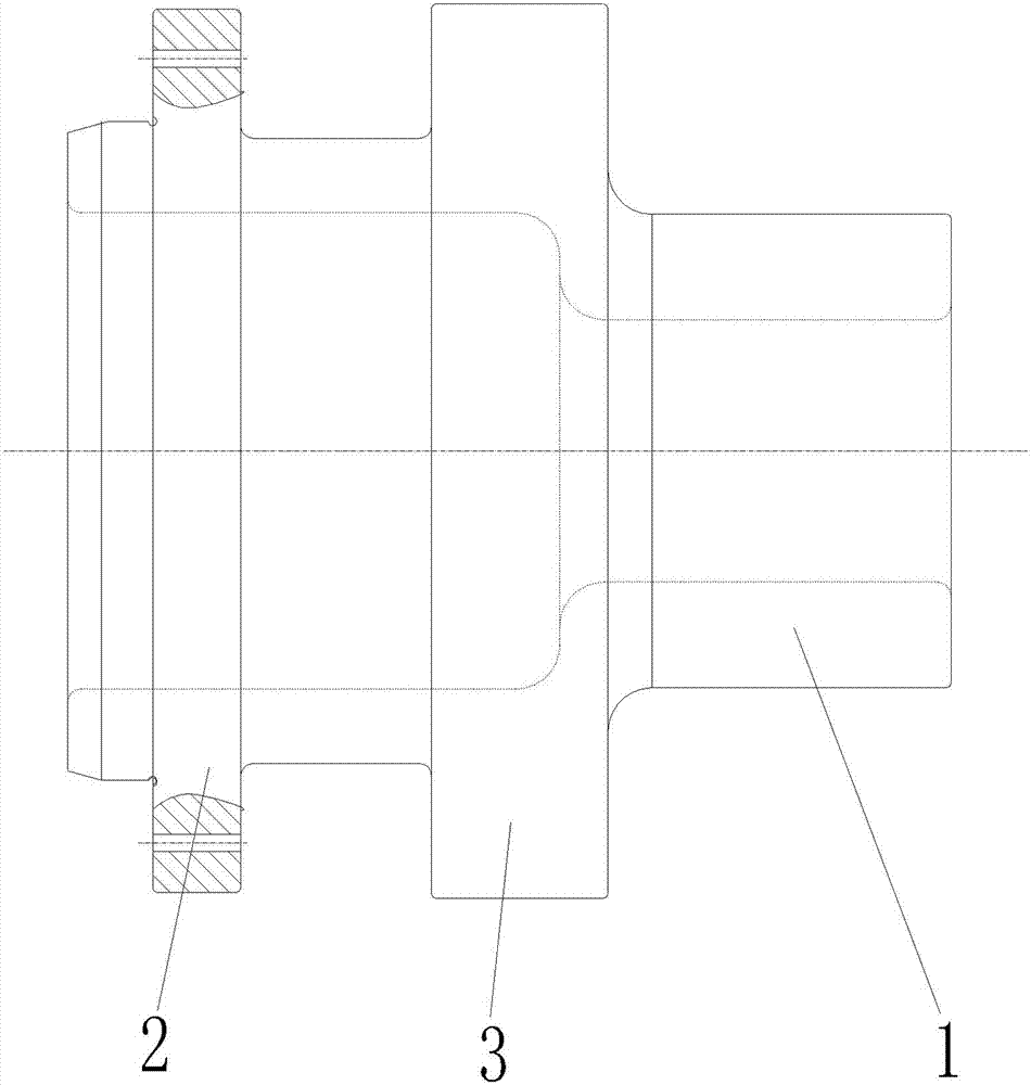
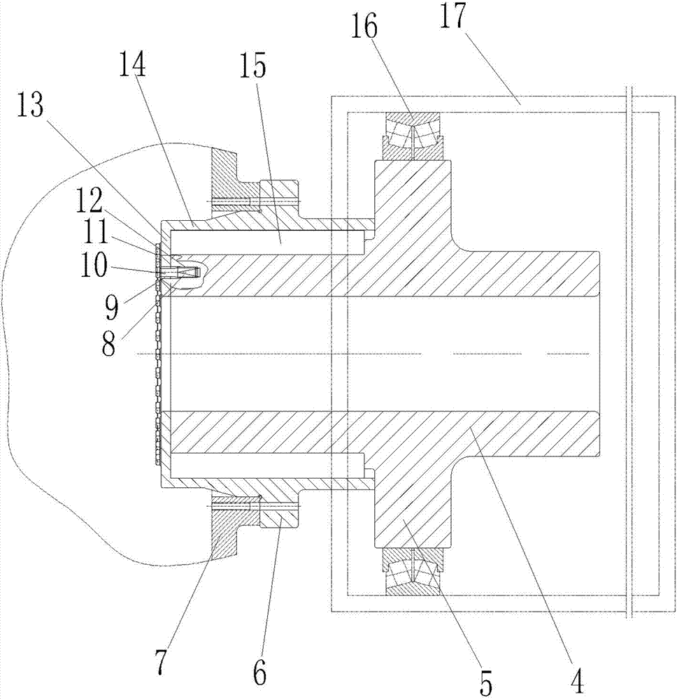
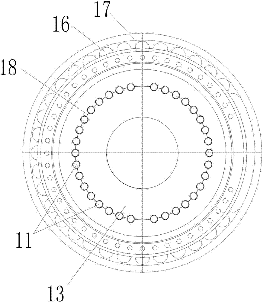
[0021] Examples of wind turbines are Figure 2~3 Shown: including the fan hub 7, the gearbox 17 and the fan main shaft connected between the fan hub 7 and the gearbox 17, the fan main shaft includes the main shaft body and the connecting flange 6 and the bearing installation ring platform 5 arranged at intervals before and after, connected The flange 6 is placed outside the casing of the gearbox 17, the connecting flange 6 is fixedly connected with the fan hub 7, the bearing mounting ring 5 is placed in the casing of the gearbox, and the bearing mounting ring and the inner wall of the casing of the gearbox A main shaft bearing 16 is provided, the input end of the gearbox is connected with the rear main body, and the output end of the gearbox is connected with the generator. The main shaft body includes a front body part and a rear body part 4 which are arranged separately and mated together. The front and rear body parts are fixedly connected by a fixed structure, and the conn...


PUM


Abstract

The invention relates to a wind driven generator and a fan main shaft thereof. The wind driven generator comprises a fan wheel hub, a gearbox, and the fan main shaft in transmission connection between the fan wheel hub and the gearbox, wherein the fan main shaft comprises a main shaft body, and a connecting flange and a bearing mounting ring table arranged at interval from front to back; the main shaft body comprises a front body part and a back body part separated in the front-back direction and inserted together; the front and back body parts are fixedly connected through a fixed structure; the connecting flange is arranged on the front body part; and the bearing mounting ring table is arranged on the back body part. The invention provides the fan main shaft easy to be produced, and the wind driven generator using the fan main shaft.

Description

technical field [0001] The invention relates to a wind power generator and a fan main shaft thereof. Background technique [0002] The wind turbine includes the hub of the wind turbine, the gearbox, and the main shaft of the fan that realizes the transmission connection between the hub of the fan and the gearbox. The main shaft of the fan is an important part of the wind turbine, and it bears the important role of supporting the suspended weight of the wind wheel assembly and transmitting power. . At present, the diameter of the wind turbines of the MW-level wind turbines in the breeze area and the wind turbines of 3MW and above are getting bigger and bigger, and the weight is also increasing, which causes the size of the connecting flange adjacent to the fan hub on the fan shaft to increase. The shaft diameter of the main shaft of the wind turbine is also increased accordingly; in addition, as people pay more and more attention to the local Hertz contact stress of the main...

Claims


Application Information

Patent Timeline
Patent Type & Authority Patents(China)
IPC IPC(8): F03D80/00
CPCF05B2240/60Y02E10/72Y02P70/50
Inventor 黄爱武刘二恩卓然仝世伟王朝东
Owner STATE GRID CORP OF CHINA
Why Eureka
Try Eureka