Self-cleaning heat dissipation type monitoring camera

A monitoring camera and heat dissipation technology, applied in the field of monitoring equipment, can solve the problems of easy adhesion of dust to the lens of the service life monitoring camera, poor heat dissipation, etc., and achieve the effect of ensuring cleanliness, fast gas flow rate, and improving the use effect.

Active Publication Date: 2020-09-11
江苏珂尔玛智控技术有限公司
View PDF6 Cites 12 Cited by
  • Summary
  • Abstract
  • Description
  • Claims
  • Application Information

AI Technical Summary

Problems solved by technology

[0004] The purpose of the present invention is to solve the disadvantages in the prior art that the monitoring camera has a poor heat dissipation ability, which affects its service life, and the lens of the monitoring camera is easy to adhere to dust, thereby affecting its use effect, and proposes a self-cleaning heat dissipation Type Surveillance Camera

Method used


Image

  • Self-cleaning heat dissipation type monitoring camera
  • Self-cleaning heat dissipation type monitoring camera
  • Self-cleaning heat dissipation type monitoring camera

Examples


Embodiment 1

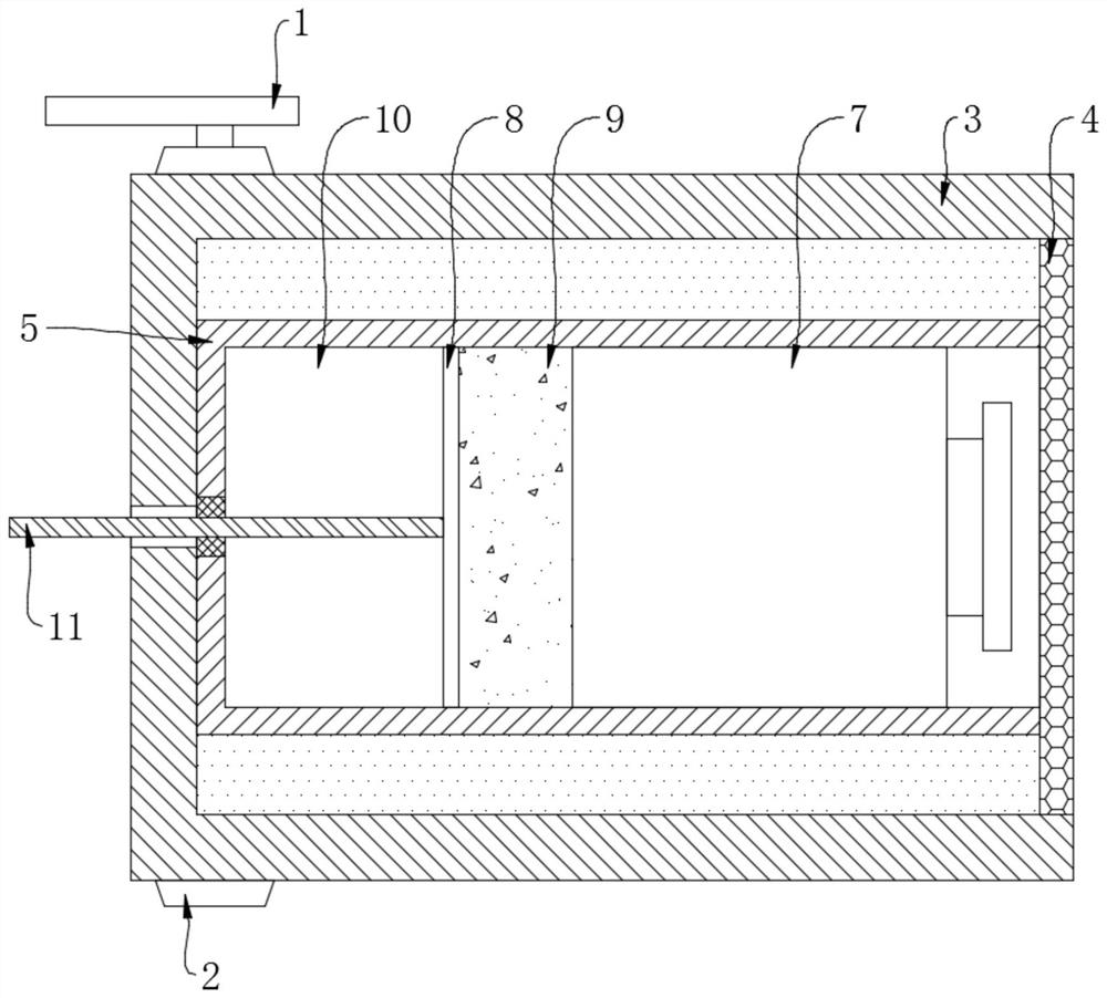
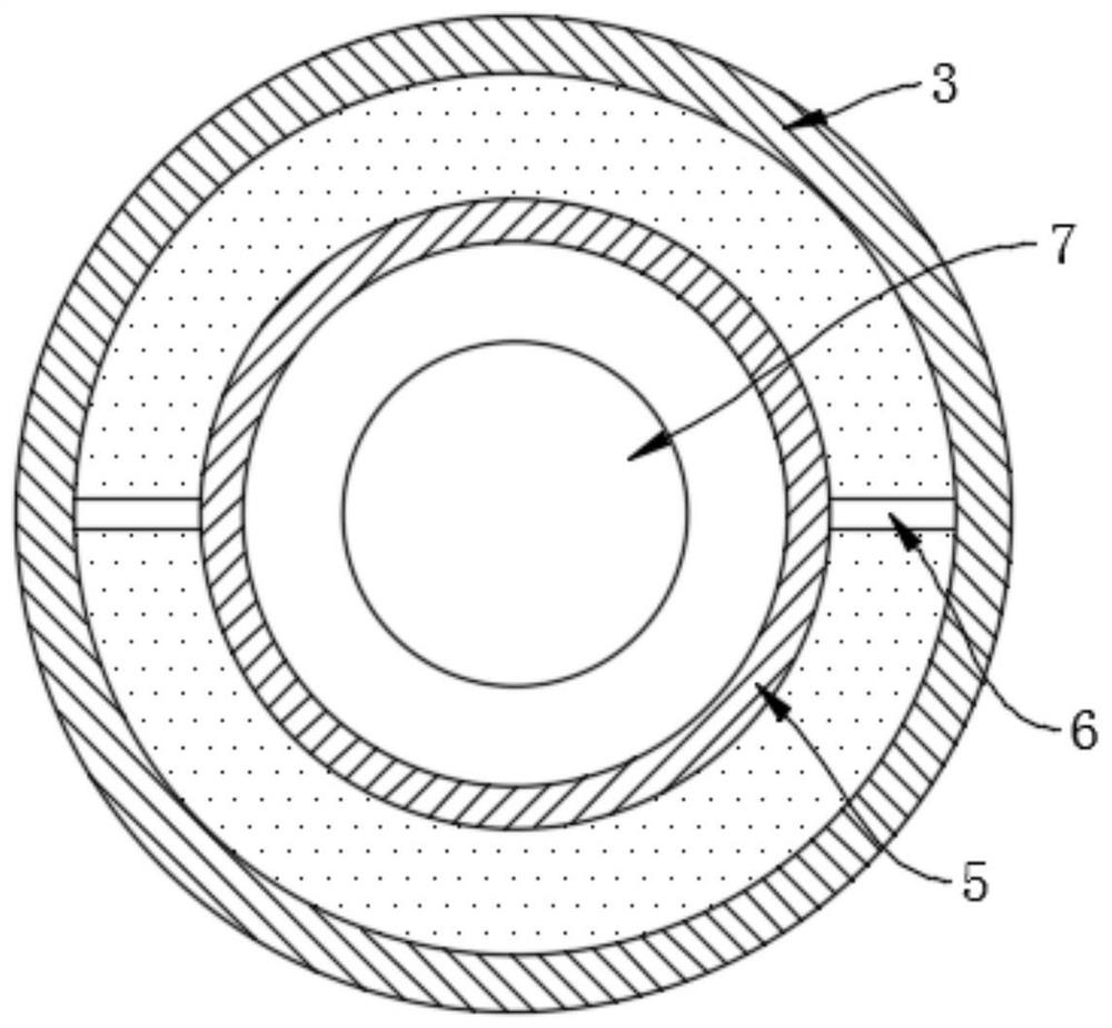
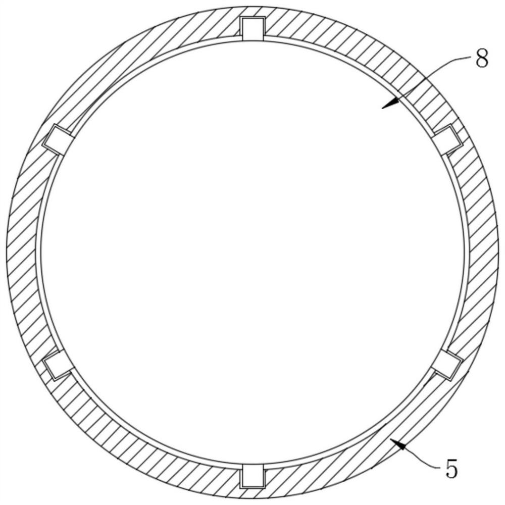
[0022] refer to Figure 1-2 , a self-cleaning and heat-dissipating monitoring camera, including a mounting base 1 and a camera body 7, a fixing ring 2 is fixed on the mounting base 1, a rotating drum 3 is fixedly installed in the fixing ring 2, and the opening of the rotating drum 3 is detachably sealed The light-transmitting plate 4 is connected, and the installation cylinder 5 is installed coaxially rotating inside the drum 3, and the opening of the installation cylinder 5 is sealed and slidingly connected with the side wall of the light-transmitting plate 4, and the outer wall of the installation cylinder 5 is symmetrically and fixedly connected with two partitions 6. The end of each partition 6 away from the corresponding installation cylinder 5 is sealed and slidably connected to the inner wall of the drum 3 , and multiple partitions 6 form a sealed space composed of the inner wall of the drum 3 , the outer wall of the installation cylinder 5 and the light-transmitting pla...

Embodiment 2

[0027] refer to Figure 4-5 The difference between this embodiment and Embodiment 1 is that: the threaded rod 11 is covered with an annular air bag 12, and the annular air bag 12 is located in the placement area 10, and the left and right side walls of the annular air bag 12 are respectively fixedly connected to the installation tube On the inner wall of 5 and the side wall of piston plate 8, the installation tube 5 is provided with the one-way exhaust pipe 13 that communicates with the annular airbag 12, and the other end opening of the one-way exhaust pipe 13 is sealed with the side wall of the light-transmitting plate 4 Slidingly connected, the light-transmitting plate 4 is provided with an air duct 14 corresponding to the one-way exhaust pipe 13, and the other end of the air duct 14 points to the center of the right side wall of the light-transmitting plate 4, and the annular airbag 12 is provided with an air duct communicating with the outside world. The one-way air intak...


PUM


Abstract

The invention discloses a self-cleaning heat dissipation type monitoring camera. The self-cleaning heat dissipation type monitoring camera comprises a mounting base and a camera body, a fixing ring isarranged on the mounting base; a rotary drum is fixedly mounted in the fixing ring; a light-transmitting plate is connected to an opening of the rotary drum in a sealed mode, an installation drum iscoaxially and rotationally installed in the rotary drum, the opening of the installation drum is connected with the side wall of the light-transmitting plate in a sealed and sliding mode, partition plates are symmetrically connected to the outer wall of the installation drum, and the end, away from the corresponding installation drum, of each partition plate is connected to the inner wall of the rotary drum in a sealed and sliding mode. A driving agent is used for driving the rotary drum to rotate back and forth, so that the plurality of cooling cavities perform heat dissipation and cooling onthe camera body in a reciprocating manner, the working temperature of the camera body is ensured to be proper, and meanwhile, the annular air bag is used for intermittently performing force storage blowing on the light-transmitting plate, so that dust adhered to the light-transmitting plate can be effectively blown off, and the use effect of the camera body is ensured.

Description

technical field [0001] The invention relates to the technical field of monitoring equipment, in particular to a self-cleaning and heat dissipation monitoring camera. Background technique [0002] At present, many surveillance cameras can often be seen near many traffic intersections or street intersections. Through the surveillance cameras, people can remotely monitor the target area for a long time, which can save a lot of manpower. Therefore, surveillance cameras have become a safe It is an indispensable and important equipment in the prevention system and traffic control system. [0003] However, in actual use, since the surveillance camera needs to work continuously, and generally its sealing is good, the heat dissipation capacity of the monitor is not good, and the heat always stays in the heat dissipation area, which cannot cool down quickly, which is easy to cause damage to the internal components of the monitor and shorten the life of the monitor. At the same time, ...

Claims


Application Information

Patent Timeline
Patent Type & Authority Applications(China)
IPC IPC(8): H04N5/225H04N7/18G03B17/55F16M13/02F16M11/10B08B1/00
CPCH04N7/18B08B1/00F16M13/02F16M11/10G03B17/55H04N23/00
Inventor 赵亚军
Owner 江苏珂尔玛智控技术有限公司
Why Eureka
Try Eureka