Dehumidification device for power equipment

A technology for power equipment and storage batteries, applied in the separation of dispersed particles, chemical instruments and methods, and filtration of dispersed particles, which can solve problems such as condensation, heating and evaporation that do not have solar power generation

Inactive Publication Date: 2020-06-02
江苏伟正电气科技有限公司
View PDF0 Cites 2 Cited by
  • Summary
  • Abstract
  • Description
  • Claims
  • Application Information

AI Technical Summary

Problems solved by technology

[0004] The purpose of the present invention is to provide a dehumidification device for electric power equipment to solve the problem that the existing dehumidification device for electric power equipment proposed in the above background technology does not have the functions of solar power generation and condensation heating and evaporation

Method used


Image

  • Dehumidification device for power equipment
  • Dehumidification device for power equipment
  • Dehumidification device for power equipment

Examples


Embodiment Construction

[0016] The following will clearly and completely describe the technical solutions in the embodiments of the present invention with reference to the accompanying drawings in the embodiments of the present invention. Obviously, the described embodiments are only some, not all, embodiments of the present invention. Based on the embodiments of the present invention, all other embodiments obtained by persons of ordinary skill in the art without making creative efforts belong to the protection scope of the present invention.

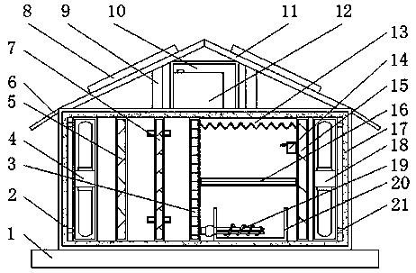
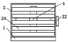
[0017] see Figure 1-4 , an embodiment provided by the present invention: a dehumidification device for electric power equipment, including a device body 2, a noise-proof rubber plate 17 and a battery 12, the bottom end of the device body 2 is provided with a base 1, and the two sides of the device body 2 are viewed from the top Air intake grille 24 is evenly arranged to the bottom, and both sides of the device body 2 above the air intake grille 24 are provide...


PUM


Abstract

The invention discloses a power equipment dehumidification device, which comprises a device body, anti-noise rubber plates and a storage battery, wherein the anti-noise rubber plates are arranged on the inner side wall of the device body, a heat exchanger is arranged between the inner walls of the anti-noise rubber plates on one side of a first filter screen, a second filter screen is arranged between the inner walls of the anti-noise rubber plates on one side of a semiconductor condensation sheet, a humidity sensor is arranged on one side of the second filter screen below a water collecting plate, an evaporator is arranged between the semiconductor condensation sheet below the humidity sensor and the second filter screen, a water tank is arranged on the inner wall of the anti-noise rubberplate below the evaporator, a heater is arranged in the water tank, and a moisture exhaust fan is arranged between the inner walls of the anti-noise rubber plates on one side of the second filter screen. According to the invention, a solar cell panel is arranged above the device body, so that the energy-saving and environment-friendly functions are realized, and the device is easy to popularize and use.

Description

technical field [0001] The invention relates to the technical field of electric equipment, in particular to a dehumidification device for electric equipment. Background technique [0002] If there is too much moisture in the working environment of the electric equipment, the life of the electric equipment will be shortened, and the danger will also be increased. Therefore, a dehumidification device is usually installed in the electric equipment. The traditional dehumidification device is to reduce the saturation of water vapor in the air by heating the air inside the power equipment to prevent condensation from forming on the surface of the power equipment, but this device does not achieve the dehumidification effect, and the moisture remains in the cabinet Inside the body, as the temperature changes, condensation will still form. And it will consume a lot of electric energy and various chemical reactions, forming secondary pollution. [0003] A traditional dehumidificatio...

Claims


Application Information

Patent Timeline
Patent Type & Authority Applications(China)
IPC IPC(8): B01D46/10B01D53/26
CPCB01D46/10B01D53/26B01D53/265
Inventor 不公告发明人
Owner 江苏伟正电气科技有限公司
Why Eureka
Try Eureka