
Metal-fiber reinforced resin material composite body and method for producing metal-fiber reinforced resin material composite body

A technology of resin materials and composites, applied in chemical instruments and methods, metal layered products, synthetic resin layered products, etc., can solve the problems of long curing time, high cost, and high price

Active Publication Date: 2020-09-11
NIPPON STEEL CORP
View PDF13 Cites 0 Cited by
  • Summary
  • Abstract
  • Description
  • Claims
  • Application Information

AI Technical Summary

Problems solved by technology

First, when painting, bending, etc., existing equipment such as painting pipelines and bending molds installed on metal members such as steel cannot be directly used for FRP
Second, due to the low compressive strength of FRP, it is difficult to directly use it in automotive components that require high compressive strength
Third, the matrix resin of FRP is generally a thermosetting resin such as epoxy resin, so it is brittle, and there is a possibility of brittle fracture if deformed
Fourth, FRP (in particular, Carbon Fiber Reinforced Plastics (CFRP: Carbon Fiber Reinforced Plastics) in which carbon fibers are used as reinforcing fibers) is expensive, which causes the cost of automotive components to increase
Fifth, as mentioned above, since a thermosetting resin is used as the matrix resin, the curing time takes a long time, and the takt time is long, so it is not suitable for the manufacture of automobile components that require a short takt time.

Method used


Image

  • Metal-fiber reinforced resin material composite body and method for producing metal-fiber reinforced resin material composite body
  • Metal-fiber reinforced resin material composite body and method for producing metal-fiber reinforced resin material composite body
  • Metal-fiber reinforced resin material composite body and method for producing metal-fiber reinforced resin material composite body

Examples


no. 1 Embodiment approach >

[0116] [Structure of metal-fiber reinforced resin material composite]

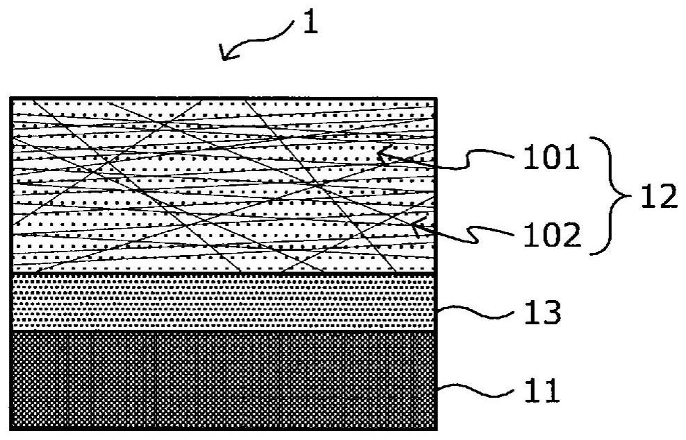
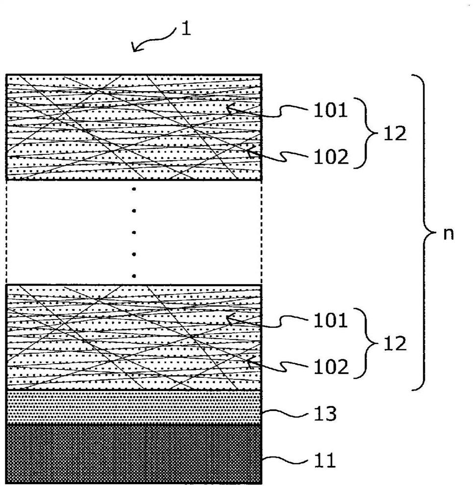
[0117] First, refer to figure 1 with figure 2 The configuration of the metal-fiber reinforced resin material composite according to the first embodiment of the present invention will be described. figure 1 with figure 2 It is a schematic diagram showing the cross-sectional structure in the lamination direction of the metal-FRP composite 1 as an example of the metal-fiber-reinforced resin material composite according to the present embodiment.

[0118] Such as figure 1 As shown, the metal-FRP composite 1 includes a metal member 11, an FRP layer 12 as an example of the first fiber-reinforced resin material according to this embodiment, and an adhesive resin layer 13. The metal member 11 and the FRP layer 12 are composited via the adhesive resin layer 13. Here, "combination" means that the metal member 11 and the FRP layer 12 (first fiber-reinforced resin material) are joined (laminated) via the adhesive resin l...

Embodiment 15

[0326] In Example 15, a hot-dip galvanized high-strength steel sheet made by Nippon Steel & Sumikin Co., Ltd., with a thickness of 0.42 mm, was used as the metal member, and this was sufficiently degreased with acetone. Next, in order to quantitatively adhere the oil component to the surface of the metal member, the rust preventive oil ダフニーオイルコート Z3 manufactured by Idemitsu Co., Ltd. was added at a rate of 5 g / m 2 Apply the amount of oil, then gently press the oil-absorbing cloth to absorb just the low amount of oil, and then use. On the metal member, the oil-surface adhesive adhesive Alphatec 370 made by Alpha Industry Co., Ltd. was used at 3g / m 2 The amount of coating. Except for the above-mentioned points, the same procedure as in Example 13 was carried out to produce a sample of a metal-CFRP composite.

Embodiment 16

[0327] In Example 16, a hot-dip galvanized high-strength steel sheet manufactured by Nippon Steel & Sumitomo Metal Co., Ltd. with a thickness of 0.42 mm was used as the metal member, and this was sufficiently degreased with acetone. Next, in order to quantitatively adhere the oil component on the surface of the metal member, the rust preventive oil ダフニーオイルコート Z3 manufactured by Idemitsu Co., Ltd. was added at a rate of 5 g / m 2 The amount is applied and then used. Prepare a mixture of finely pulverized Mitsui Chemicals Admate QE06050 parts by mass, and Alfumec 370 manufactured by Alpha Industry Co., Ltd. as an oil-face adhesive adhesive, and a mixture of 50 parts by mass mixed in a mass ratio of 100:30 Parts by mass, the mixture is further mixed with Mitsui Chemicals’ Adma QE060 at 4g / m 2 The amount is coated on the metal member. Except for the above-mentioned points, a sample of a metal-CFRP composite was produced in the same manner as in Example 13.


PUM

PropertyMeasurementUnit
Melt viscosityaaaaaaaaaa

Abstract

An aim of the invention is to bond a metal member and a fiber reinforced resin material, which uses a thermoplastic phenoxy resin as a matrix resin, with each other without decreasing the performanceof the fiber reinforced resin material; and to suppress the occurrence of electrolytic corrosion between the metal member and the fiber reinforced resin material. [Solution] A metal-fiber reinforced resin material composite body according to the present invention is provided with: a metal member; a fiber reinforced resin material which is superposed on at least one surface of the metal member so as to be complexed with the metal member; and a bonding resin layer which is interposed between the metal member and the fiber reinforced resin material. The fiber reinforced resin material comprises amatrix resin that contains 50 parts by mass or more of a phenoxy resin in 100 parts by mass of the resin component and a reinforcing fiber material that is contained in the matrix resin; the concentration of the phenoxy resin in the resin component of the bonding resin layer is lower than the concentration of the phenoxy resin in the resin component of the matrix resin; and the shear strength between the metal member and the fiber reinforced resin material is 0.8 MPa or more.

Description

Technical field [0001] The present invention relates to a method for manufacturing a metal-fiber reinforced resin material composite and a metal-fiber reinforced resin material composite. Background technique [0002] Fiber Reinforced Plastics (FRP: Fiber Reinforced Plastics) in which a matrix resin contains reinforcing fibers (for example, glass fibers, carbon fibers, etc.) are compounded with light weight and excellent tensile strength, processability, and the like. Therefore, it is widely used from people's livelihood to industrial applications. In the automotive industry, it also meets the needs of vehicle body weight reduction related to the improvement of fuel economy and other performance. Therefore, focusing on the light weight, tensile strength, and processability of FRP, the application of FRP to automotive components has been studied. [0003] In the case of using FRP itself as an automobile component, for example, there are various problems as follows. First, when pai...

Claims


Application Information

Patent Timeline
IPC IPC(8): B32B15/14B32B15/08B32B15/092C08J5/24C08K7/02B62D29/04C08L71/12
CPCC08L71/12B62D29/04C08J2371/00C08J5/041C08J5/242B32B7/12B32B15/14B32B5/02B32B2307/542B32B2307/50B32B27/26B32B33/00B32B2605/08B32B15/18B32B2250/02B32B2307/54B32B27/34B32B2262/106B32B27/365B32B2260/021B32B2307/732B32B2307/714B32B2307/51B32B2255/205B32B15/20B32B27/12B32B5/022B32B2260/046B32B2255/06B32B15/085B32B2250/03B32B27/32B32B7/022B32B15/08C08L71/10
Inventor 茨木雅晴祢宜教之臼井雅史中井雅子
Owner NIPPON STEEL CORP
Learn More