Bridging dissection locking bone plate for fixing comminuted fracture of humerus shaft on rear outer side

A technology of comminuted fractures and bone plates, which is applied in the field of medical equipment, can solve problems such as hyposensation or disappearance of the skin on the radial side of the arm, radial nerve injury, forearm supination disorder, etc., and reduce the risk of bleeding and nerve damage. Reasonable design and less screw holes

Inactive Publication Date: 2020-09-15
JILIN UNIV FIRST HOSPITAL
View PDF0 Cites 1 Cited by
  • Summary
  • Abstract
  • Description
  • Claims
  • Application Information

AI Technical Summary

Problems solved by technology

[0003] The existing bone plate used for the fixation of humeral shaft comminuted fracture mainly has the following two problems: 1. Extensive soft tissue needs to be peeled off, and the destruction of periosteal blood supply around the fracture often leads to a high rate of fracture nonunion; 2. After internal fixation, the radial nerve is located on the surface of the bone plate, causing the radial nerve to be rubbed and squeezed for a long time, which may easily cause radial nerve damage in the long run. Inability to dorsiflexion, forearm supination disorder, and decreased or disappeared skin sensation on the radial side of the arm, etc. In severe cases, the quality of life of the patient will be significantly reduced

Method used


Image

  • Bridging dissection locking bone plate for fixing comminuted fracture of humerus shaft on rear outer side
  • Bridging dissection locking bone plate for fixing comminuted fracture of humerus shaft on rear outer side
  • Bridging dissection locking bone plate for fixing comminuted fracture of humerus shaft on rear outer side

Examples


Embodiment Construction

[0023] The present invention will be described in further detail below in conjunction with specific embodiments and accompanying drawings.

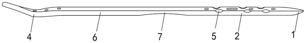
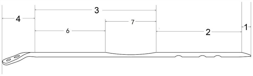
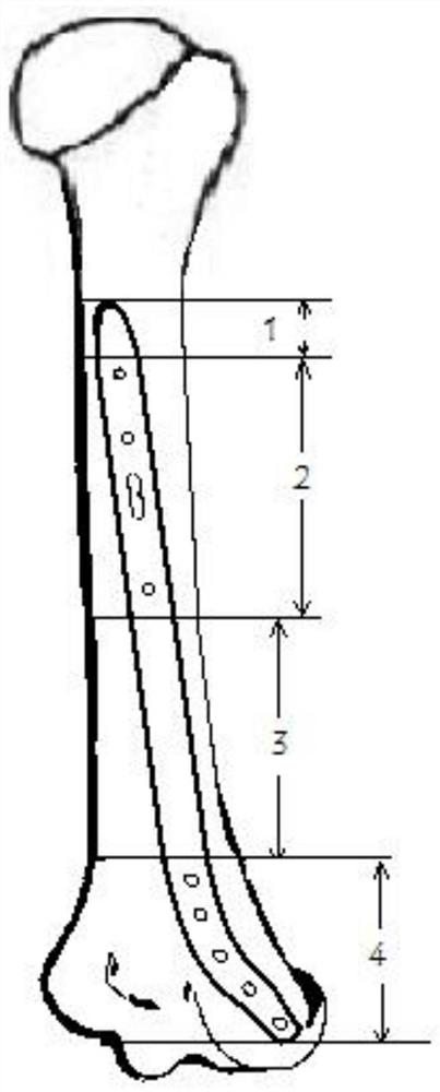
[0024] Such as figure 1 and 2 As shown, the present invention provides a bridging anatomical locking bone plate for posterolateral fixation of humeral shaft comminuted fractures, comprising a bone plate body, the inner surface of the bone plate body is fitted behind the humeral shaft and the lateral epicondyle of the humerus The anatomical structure matches the side surface; it is characterized in that the bone plate body includes a tapered periosteum dissection zone 1, a first fixation zone 2, a radial nerve decompression zone 3 and a conical periosteum dissection zone from the proximal end to the distal end Two fixation areas 4, the longitudinal section of the tapered periosteal dissection area 1 is a right-angled triangle, and a right-angled side of the right-angled triangle fits on the surface of the humerus shaft; A plurality of lo...


PUM


Abstract

The invention provides a bridging dissection locking bone plate for fixing comminuted fracture of a humerus shaft on the rear outer side. The inner surface of a bone plate body is attached to the rearside surface of the humerus shaft and the external epicondyle of the humerus, and a dissection structure is matched with the bone fracture plate body; the bone plate body sequentially comprises a tapered periosteum stripping area, a first fixing area, a radial nerve decompression area and a second fixing area from the near end to the far end, the longitudinal section of the tapered periosteum stripping area is a right triangle, and one right-angle side of the right triangle is attached to the surface of the humerus shaft; the first fixing area is provided with a plurality of locking screw holes and locking and pressurizing combination screw holes which are perpendicular to the surface of the humerus shaft which is attached to the first fixing area; and a groove is formed in the outer surface of the radial nerve decompression area, and the edge of the groove is an arc-shaped transition area; the shape of the second fixing area is matched with that of a distal humeral epicondyle anatomical structure, and a plurality of locking screw holes are formed in the second fixing area in the length direction. In the process of fixing the comminuted fracture of the humerus shaft, blood supplyof the broken end of the fracture is not damaged, nerves are not damaged, and operation time is short.

Description

technical field [0001] The invention belongs to the field of medical equipment used in orthopedic surgery, in particular to a bridging anatomical locking bone plate for posterolaterally fixing comminuted humeral shaft fractures. Background technique [0002] For comminuted fractures of the humeral shaft, especially those where the fracture line extends to 1 / 3 of the distal end of the humerus, there is little space for the bone plate to hold the distal end of the fracture, making fixation very difficult. There is a bony radial nerve groove behind the middle part of the humeral shaft, through which the radial nerve passes, and the distal end of the humerus becomes flattened and widened, triangular in shape and angled forward. There is an olecranon fossa in the rear of the distal humerus, a coronal fossa in the front, and an ulnar nerve groove in the medial side, through which the ulnar nerve passes. Although there are minimally invasive bone plate techniques ( MIPO) in the tr...

Claims


Application Information

Patent Timeline
Patent Type & Authority Applications(China)
IPC IPC(8): A61B17/80
CPCA61B17/8057A61B17/8061A61B17/808A61B2017/564
Inventor 孙大辉王子航刘岩林童赵天昊杨光刘哲闻
Owner JILIN UNIV FIRST HOSPITAL
Why Eureka
Try Eureka