Volatile contaminated soil remediation integrated device
A volatile pollution and soil remediation technology, applied in the field of contaminated soil treatment, can solve the problems of incomplete soil remediation, unfavorable improvement of soil quality, volatile, etc., to achieve the effect of promoting thorough remediation, improving quality, and realizing separation
- Summary
- Abstract
- Description
- Claims
- Application Information
AI Technical Summary
Problems solved by technology
Method used
Image
Examples
Embodiment
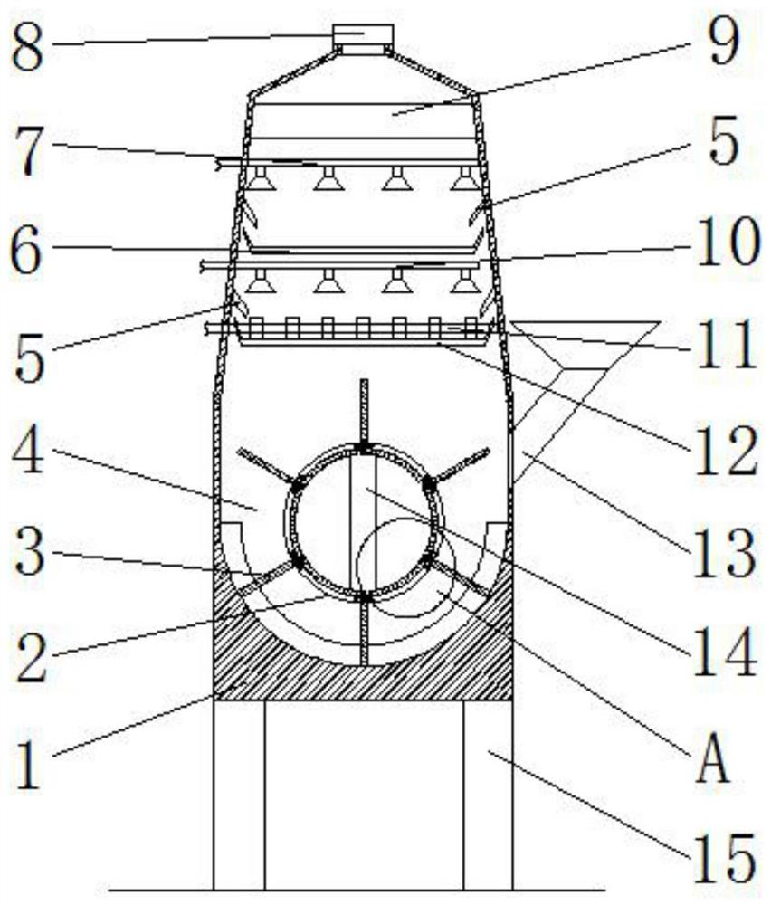
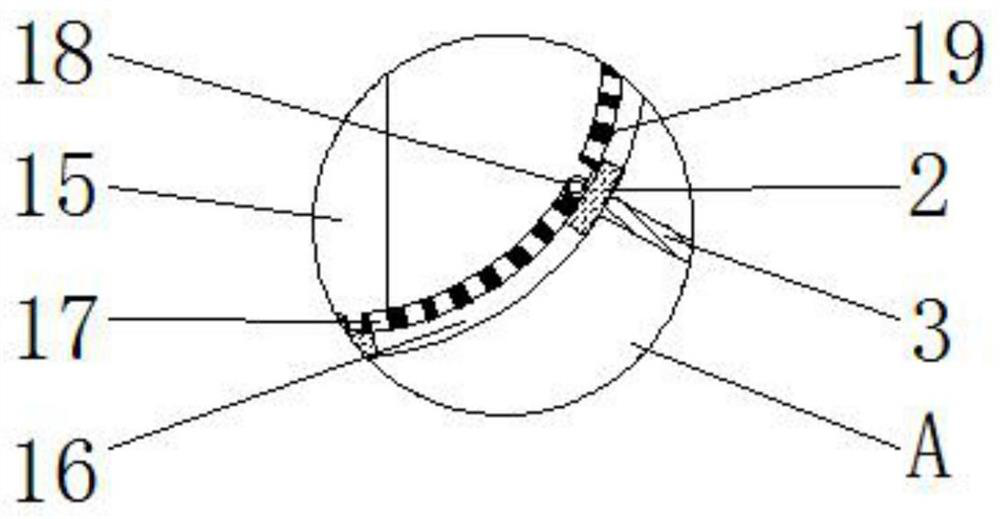
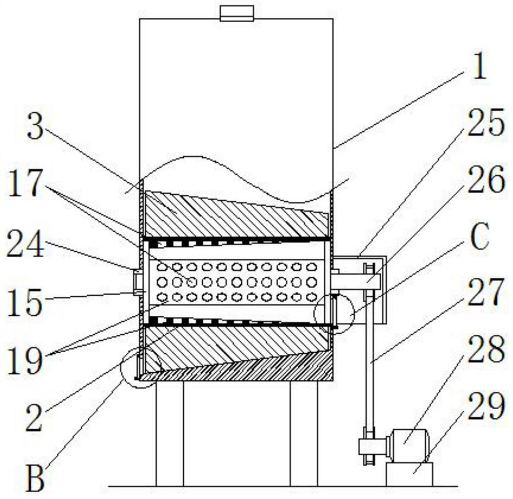
[0029] Such as figure 1 The shown integrated device for remediation of volatile contaminated soil includes an outer shell 1 with a supporting leg 15 at the bottom. The outer shell 1 is provided with a soil storage cavity 4, an ozone oxidation mechanism, and a neutralization spray from bottom to top. The drenching mechanism and the adsorption mechanism 9, one side of the outer shell 1 is provided with a feed port 13 communicating with the soil storage cavity 4, and the ozone oxidation mechanism includes an ozone oxidation water storage tank 12, and an aerator located in the ozone oxidation water storage tank 12 The gas plate 11 and the ozone oxidation water spray pipe 10 directly above the ozone oxidation water storage tank 12, the neutralization spray mechanism includes a liquid collection tank 6 and a neutralization liquid spray tube 7 directly above the liquid collection tank 6, The adsorption mechanism 9 includes activated carbon filled, the upper sides of both sides of the o...
Embodiment 2
[0039] The difference between this embodiment and Embodiment 1 is:
[0040] In this embodiment, as figure 1 As shown, the corresponding side of the outer shell 1 on which the baffle 5 is located is inclinedly arranged above the soil storage cavity 4, and the distance between the corresponding two sides gradually decreases from bottom to top. The corresponding parts of the outer shell 1 are arranged obliquely and gathered upwards, which can promote the gathering of volatile gases to the middle, and the length of the treated area above the gas is small, so that the products and residues (solid and liquid) in the spray treatment process ) Can completely fall into the corresponding tank body when it is dropped, thereby avoiding secondary pollution caused by the products and residues falling into the soil during the aforementioned spray treatment process.
[0041] Others are the same as in Example 1.
Embodiment 3
[0043] The difference between this embodiment and Embodiment 1 is:
[0044] In this embodiment, as Image 6 As shown, the part of the outer casing 1 corresponding to the area where the ozone oxidation mechanism and the neutralization spray mechanism are located is a cylindrical shape with a convex middle part on the side surface. The soil storage cavity 4, the ozone oxidation mechanism, the neutralization spray mechanism and the adsorption mechanism 9 Two partitions are separated by partitions 21. Each partition 21 is provided with a communication port 20 on one side, and the communication ports 20 on every two adjacent partitions 21 are located on two opposite sides, below The communication ports 20 on the two partitions 21 of the two partitions are all inclined toward the corresponding side inner wall of the outer shell 1 above them; the top of the suction mechanism 9 is provided with a blocking plate 22, which faces away from the suction mechanism 9 There is a gap between one...
PUM
 Abstract
Description
Claims
Application Information
 - R&D
- Intellectual Property
- Life Sciences
- Materials
- Tech Scout
- Unparalleled Data Quality
- Higher Quality Content
- 60% Fewer Hallucinations
Browse by: Latest US Patents, China's latest patents, Technical Efficacy Thesaurus, Application Domain, Technology Topic, Popular Technical Reports.
© 2025 PatSnap. All rights reserved.Legal|Privacy policy|Modern Slavery Act Transparency Statement|Sitemap|About US| Contact US: help@patsnap.com


