Wall surface spraying machinery and operating equipment

A technology of machinery and paint boxes, applied in the fields of filtration and separation, chemical instruments and methods, construction, etc., can solve the problems of easy clogging of nozzles, inability to dry, easy adhesion of dust, etc., and achieve good retention effect and avoid condensation.

Inactive Publication Date: 2020-09-15
鲁仲斐
View PDF10 Cites 0 Cited by
  • Summary
  • Abstract
  • Description
  • Claims
  • Application Information

AI Technical Summary

Problems solved by technology

However, after the device is sprayed, the mortar and other materials on the wall are in a wet state. If the paint is sprayed, it cannot be dried, so it

Method used


Image

  • Wall surface spraying machinery and operating equipment
  • Wall surface spraying machinery and operating equipment
  • Wall surface spraying machinery and operating equipment

Examples


Example Embodiment

[0023] Example 1

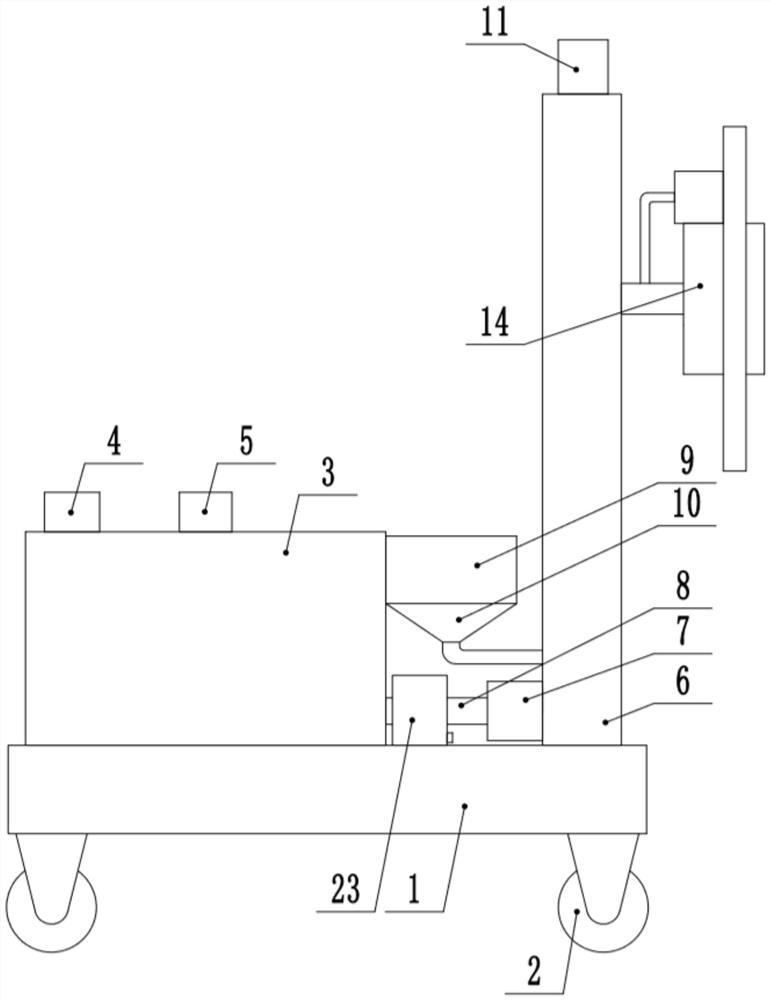
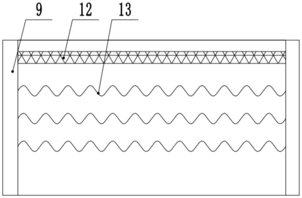
[0024] see Figure 1-5 , a wall spraying machine, comprising a bottom plate 1, the four corners of the bottom of the bottom plate 1 are fixed with roommate moving wheels 2, the top end of the bottom plate 1 is fixedly connected to the paint box 3, and the top end of the paint box 3 is fixedly provided with a feed hopper 4 , the top of the paint tank 3 is fixedly connected to the stirring motor 5, the output shaft of the stirring motor 5 passes through the paint tank 3 and is fixedly connected to the stirring rod, the other end of the top of the bottom plate 1 is fixedly connected to the lifting frame 6, and the lifting frame 6 is provided with a lifting mechanism. The lifting mechanism is connected to the spraying and drying device 14 , and one side of the paint tank 3 is provided with a hot air device and a filter device 24 .

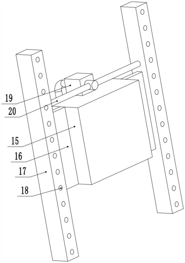
[0025] The lifting mechanism includes a lifting motor 11 fixedly arranged on the top of the lifting frame 6, the output shaft of t...

Example Embodiment

[0029] Example 2

[0030] see Figure 1-5 , a wall spraying machine, comprising a bottom plate 1, the four corners of the bottom of the bottom plate 1 are fixed with roommate moving wheels 2, the top end of the bottom plate 1 is fixedly connected to the paint box 3, and the top end of the paint box 3 is fixedly provided with a feed hopper 4 , the top of the paint tank 3 is fixedly connected to the stirring motor 5, the output shaft of the stirring motor 5 passes through the paint tank 3 and is fixedly connected to the stirring rod, the other end of the top of the bottom plate 1 is fixedly connected to the lifting frame 6, and the lifting frame 6 is provided with a lifting mechanism. The lifting mechanism is connected to the spraying and drying device 14 , and one side of the paint tank 3 is provided with a hot air device and a filter device 24 .

[0031] The lifting mechanism includes a lifting motor 11 fixedly arranged on the top of the lifting frame 6, the output shaft of t...


PUM


Abstract

The invention discloses wall surface spraying machinery and relates to the field of machinery. The wall surface spraying machinery comprises a bottom plate; moving wheels are fixedly arranged at fourcorners of the bottom plate, respectively; one end of the top of the bottom plate is fixedly connected with a coating box; a feed hopper is fixedly arranged at one end of the top of the coating box; astirring motor is fixedly connected to the top end of the coating box; an output shaft of the stirring motor penetrates through the coating box and is fixedly connected with a stirring rod; the otherend of the top of the bottom plate is fixedly connected with a lifting frame; a lifting mechanism is arranged in the lifting frame and is connected with a spraying and drying device; and a hot air device and a filtering device are arranged on one side of the coating box. According to the wall surface spraying machinery in the invention, blocky materials bonded in the coating can be filtered by the filtering device, so that a spray head is prevented from being blocked during conveying and spraying; and hot air is blown to dry a wall surface after the wall surface is sprayed by the spraying anddrying device and the coating in a pipeline can be heated in the hot air blowing process at the same time, so that the coating is prevented from being condensed in the conveying process, and the state maintaining effect on the coating is good.

Description

technical field [0001] The invention relates to the field of machinery, in particular to a wall spraying machine and operating equipment. Background technique [0002] In building construction, in order to level the wall, protect the wall or modify it, paint is usually sprayed on the outer surface of the wall made of red brick or concrete. [0003] In the Chinese invention patent document with the notification number CN103628662B, a wall spraying machine and operating equipment are announced. When the device is working, the wall spraying machine is moved to a predetermined position, and the nozzle is connected to the outlet of the mortar pump. , and then, the first driving mechanism drives the boom to move to the working position. In the working position, the spray head is aimed at the wall and keeps an appropriate distance from the wall. Finally, the mortar pump is started to provide mortar for the wall spraying machine. During the spraying process, the spraying point of t...

Claims


Application Information

Patent Timeline
IPC IPC(8): E04F21/08E04F21/16B01D35/02
CPCB01D35/02E04F21/08E04F21/16
Inventor 鲁仲斐胡嘉侃
Owner 鲁仲斐
Why Eureka
Try Eureka