A smart filter
A filter element, intelligent technology, applied in the flow control of auxiliary non-electric power, the installation/connection of lubricant purification devices, lubricating parts, etc., can solve problems such as reducing the service life of the engine, affecting the aging of oil cleaning, and accelerating the wear of parts , to achieve the effect of extending the service life, convenient maintenance and replacement, and keeping clean and aging
- Summary
- Abstract
- Description
- Claims
- Application Information
AI Technical Summary
Problems solved by technology
Method used
Image
Examples
Embodiment 1
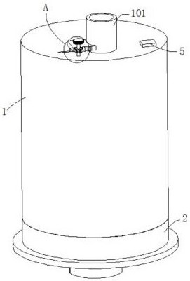
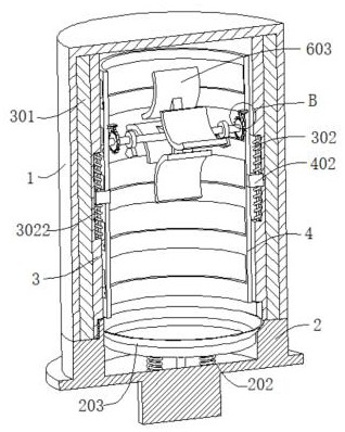
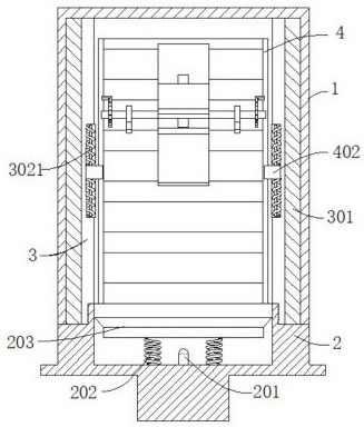
[0034] refer to Figure 1-5 , an intelligent filter element, comprising a filter element shell 1 and a base 2, the base 2 is connected to the bottom of the filter element shell 1, the inner wall of the filter element shell 1 is connected with a filter element inner tube 3, the base 2 is detachably connected to the bottom of the filter element inner tube 3, the filter element shell 1 A filter paper ring 301 is connected between the inner wall and the outer wall of the filter element inner tube 3, the top of the filter element shell 1 is connected with an oil inlet 101, the inner wall of the filter element inner tube 3 is slidingly connected with a scraper ring 4, and the scraper ring 4 is connected to the filter element inner tube 3 The activities are balanced, the inner wall of the scraper ring 4 is connected with a swing mechanism, the inner wall of the base 2 is connected with a control switch 201, and the inner wall of the base 2 is connected with two first elastic elements ...
Embodiment 2
[0037] refer to Figure 1-5, an intelligent filter element, which is basically the same as Embodiment 1, furthermore, an intelligent filter element, comprising a filter element shell 1 and a base 2, the base 2 is connected to the bottom of the filter element shell 1, and the inner wall of the filter element shell 1 is connected with a filter element inner tube 3. The base 2 is detachably connected to the bottom of the filter element inner tube 3. A filter paper ring 301 is connected between the inner wall of the filter element shell 1 and the outer wall of the filter element inner tube 3. The top of the filter element shell 1 is connected to an oil inlet 101. The inner wall of the filter element inner tube 3 Slidingly connected with a scraper ring 4, the scraper ring 4 is movable against the inner tube 3 of the filter element, the inner wall of the scraper ring 4 is connected with a swing mechanism, the inner wall of the base 2 is connected with a control switch 201, and the in...
Embodiment 3
[0040] refer to figure 1 , Figure 6 , Figure 7 and Figure 8 , an intelligent filter core, which is basically the same as that of Embodiment 1, furthermore, the inner wall of the scraper ring 4 is connected with a support seat 7, and the inner wall of the support seat 7 is connected with a baffle 701 through a hinge, and the baffle 701 is connected with the support seat 7 A third elastic element 702 is connected between the inner walls, a ratchet gear 8 is connected to the outer wall of the fixed shaft 6, and the baffle plate 701 is movable against the ratchet gear 8; the ratchet gear 8 is limited by the baffle plate 701, so that the fixed shaft 6 can only move along the Rotate in one direction to avoid the random rotation of the fixed shaft 6, which will affect the cleaning effect of the scraper ring 4.
[0041] The inner wall of the inner tube 3 of the filter element is fixed with an internal thread 303, and the outer wall of the base 2 is fixed with an external thread ...
PUM
 Abstract
Description
Claims
Application Information
 - R&D
- Intellectual Property
- Life Sciences
- Materials
- Tech Scout
- Unparalleled Data Quality
- Higher Quality Content
- 60% Fewer Hallucinations
Browse by: Latest US Patents, China's latest patents, Technical Efficacy Thesaurus, Application Domain, Technology Topic, Popular Technical Reports.
© 2025 PatSnap. All rights reserved.Legal|Privacy policy|Modern Slavery Act Transparency Statement|Sitemap|About US| Contact US: help@patsnap.com


