Self-pressurized pressurizing oil tank

A pressurized fuel tank and self-pressurized technology, which is applied to fuel supply tank devices, fluid pressure converters, mechanical equipment, etc., can solve the problems of limiting system performance, low stability, and inability to guarantee the oil absorption performance of hydraulic pumps. Achieve the effect of ensuring oil absorption performance, avoiding air suction, and improving sealing reliability

Pending Publication Date: 2020-09-15
贵州航天控制技术有限公司
View PDF0 Cites 0 Cited by
  • Summary
  • Abstract
  • Description
  • Claims
  • Application Information

AI Technical Summary

Problems solved by technology

[0005] The purpose of the present invention is to provide a new type of pressurized oil tank to solve the problem of simple structure and low stability of the double pressurized spring structure, especially in high-speed electro-hydraulic servo systems with hydraulic pump speeds exceeding 12000r / min. The oil absorption performance of the hydraulic pump cannot be guaranteed, which limits the performance of the system

Method used


Image

  • Self-pressurized pressurizing oil tank
  • Self-pressurized pressurizing oil tank
  • Self-pressurized pressurizing oil tank

Examples


Embodiment Construction

[0026] In order to make the technical problems, technical solutions and beneficial effects to be solved by the present invention clearer, the present invention will be further described in detail below in conjunction with the accompanying drawings and embodiments. It should be understood that the specific embodiments described here are only used to explain the present invention, not to limit the present invention.

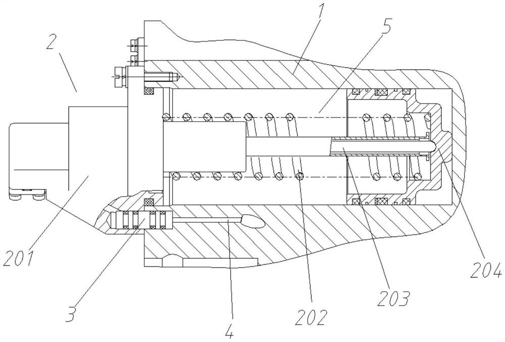
[0027] Such as Figures 1 to 2 As shown, this embodiment discloses a self-pressurizing pressurized fuel tank, which includes a fuel tank shell 1 and a booster device 2 arranged on the fuel tank shell 1 .

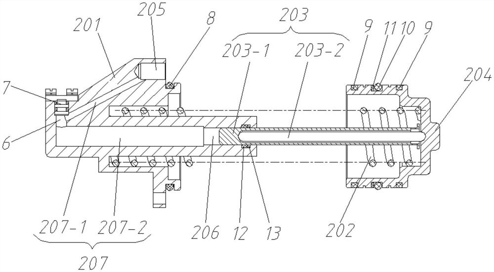
[0028] Such as figure 2 As shown, the booster device 2 includes a fuel tank rear cover 201 , an elastic element 202 , a plunger assembly 203 and a booster piston 204 . The fuel tank rear cover 201 is installed on the fuel tank shell 1 through bolts, and the first sealing ring 8 is arranged on the outer wall of the circumference of the installation part of the ...


PUM


Abstract

The invention discloses a self-pressurized pressurizing oil tank which comprises an oil tank housing and a pressurizing device. The pressurizing device comprises an oil tank back cover, wherein the oil tank back cover is hermetically connected to the oil tank housing, an oil inlet and a plunger guide hole are formed in the oil tank back cover, the oil inlet communicates to the plunger guide hole through a communicating channel pre-arranged in the oil tank back cover, and the oil inlet is in abutted communication to a high pressure oilway pre-arranged in the oil tank housing; a pressurizing plunger assembly capable of stretching is arranged in the plunger guide hole, an exposed end of the plunger guide hole leans against a pressurizing piston, an elastic component is arranged on the periphery of the pressurizing plunger assembly, and two ends of the elastic component lean against the oil tank back cover and the pressurizing piston, separately. By adopting a self-pressurizing mode, the self-pressurized pressurizing oil tank can provide a high pressure in a working state of a system to guarantee a self-suction property of a hydraulic pump in a high rotating speed condition and keep relatively low pressure in a non-working state to provide long-term storage sealing reliability.

Description

technical field [0001] The invention relates to the technical field of pressurized fuel tanks, in particular to a self-pressurized pressurized fuel tank. Background technique [0002] As an important part of the integrated electro-hydraulic servo system, the pressurized oil tank has the functions of storing and providing a certain pressure of working medium, heat dissipation and compensation. [0003] The existing pressurized oil tank generally adopts a double booster spring structure to act on the fuel tank piston, and the pressurization is realized through the pre-compression design of the booster spring. It has the characteristics of simple structure, but it has high requirements for the stability of the booster spring. During long-term work or long-term storage, it is inevitable that there will be pressure changes caused by plastic deformation, especially in the case of high pressure, the higher the stiffness of the booster spring The higher the requirements for the sta...

Claims


Application Information

Patent Timeline
IPC IPC(8): F15B1/26F15B3/00
CPCF15B1/26F15B3/00
Inventor 寸有超张康军李天齐张浩然刘文范玉浪李中金
Owner 贵州航天控制技术有限公司
Why Eureka
Try Eureka