
Variable segment LFM waveform generation and optimization method

A waveform generation and waveform optimization technology, applied in the field of radar waveform design, can solve problems such as not being well applicable to MIMO radar systems, insufficient freedom and flexibility of PLFM signals, and complex modulation methods, and achieve a large degree of design freedom and flexibility. The effect of stability, continuous frequency change and good orthogonality

Active Publication Date: 2020-09-15
XIDIAN UNIV
View PDF2 Cites 3 Cited by
  • Summary
  • Abstract
  • Description
  • Claims
  • Application Information

AI Technical Summary

Problems solved by technology

[0004] However, the disadvantage of method 1 is that there are only two sets of orthogonal waveforms, which are only suitable for MIMO radar with two-shot system; the frequency diversity method provided by method 2 has a low utilization rate of bandwidth, and the modulation method is complicated and difficult to generate; method 3 provides PLFM signal does not have enough freedom and flexibility in design, so it cannot be well applied to MIMO radar system

Method used


Image

  • Variable segment LFM waveform generation and optimization method
  • Variable segment LFM waveform generation and optimization method
  • Variable segment LFM waveform generation and optimization method

Examples


Embodiment 1

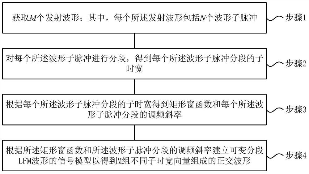
[0062] See figure 1 , figure 1 It is a schematic diagram of a variable segment LFM waveform generation method provided by an embodiment of the present invention, including:

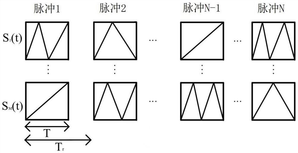
[0063] Step 1: Acquire M transmit waveforms; wherein, each transmit waveform includes N waveform sub-pulses;

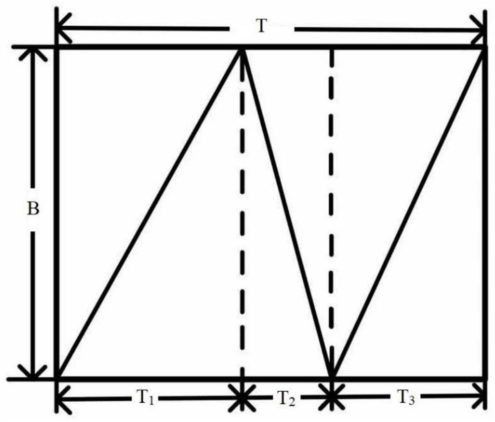
[0064] Step 2: Segmenting each of the waveform sub-pulses to obtain the sub-time width of each of the waveform sub-pulses;

[0065] Specifically, the sub-time width of the waveform sub-pulse segment is expressed as:

[0066]

[0067] Among them, T mni Indicates the sub-time width of the i-th segment of the n-th sub-pulse of the m-th transmission waveform, m=1,2,...,M, M represents the number of transmission waveforms, n=1,2,...,N, N represents Waveform sub-pulse number, i=1,2,...,I, I represents the maximum sub-time width segment number, T represents the sub-pulse width, P represents the number of pulse width discrete codes, c mni Represents the encoding vector of the sub-time width of th...

Embodiment 2

[0084] On the basis of the first embodiment above, this embodiment also provides a method for optimizing variable segmented LFM waveforms, please refer to Figure 4 , Figure 4 It is a schematic diagram of a variable segmented LFM waveform optimization method provided by an embodiment of the present invention, including:

[0085] S1: Acquire the signal model of the variable segmented LFM waveform to obtain M sets of orthogonal waveforms.

[0086] Specifically, the signal model of the variable segmented LFM waveform provided by the first embodiment above is obtained, and M sets of orthogonal waveforms are obtained.

[0087] S2: Calculate the autocorrelation sequence and cross-correlation sequence of each group of orthogonal waveforms to obtain the optimization index of each group of orthogonal waveforms; wherein, each group of orthogonal waveforms includes two optimization indexes, which are the peak value of the autocorrelation side lobe level ASPL and cross-correlation peak...

Embodiment 3

[0133] The beneficial effects of the present invention will be further compared and illustrated through simulation experiments below.

[0134] Simulation conditions:

[0135] In this simulation experiment, set the number of signals M=4, the signal bandwidth B=1.65MHz, and the center frequency is f 0 =0, sub-pulse duration T p =100μs, the pulse repetition interval is T r =1000μs, the number of sub-pulses N=32, the maximum number of sub-time widths is I=4, the maximum evolution algebra G=300 generations, the population size Np=50, and the crossover probability is P c =0.75, the mutation probability is P m =0.25, weight coefficient w m = 1,w ml =1.


PUM


Abstract

The invention discloses a variable segment LFM waveform generation and optimization method, and the method comprises the steps: obtaining M transmitting waveforms, wherein each transmitting waveform comprises N waveform sub-pulses; segmenting each waveform sub-pulse to obtain a sub-time width of each waveform sub-pulse segment; obtaining a rectangular window function and a frequency modulation slope of each waveform sub-pulse segment according to the sub-time width of each waveform sub-pulse segment; and according to the rectangular window function and the frequency modulation slope of each waveform sub-pulse segment, establishing a signal model of a variable segment LFM waveform so as to obtain an orthogonal waveform composed of M groups of different sub-time-width vectors. The variable segment LFM waveform provided by the invention simultaneously adopts frequency modulation time width diversity and segment number diversity, and the sub-time width length and the segment number are variable, so that the variable segment LFM waveform has higher design freedom degree and flexibility, is simple to modulate and easy to generate, and is more suitable for a multi-emission system of an MIMO radar system.

Description

technical field [0001] The invention belongs to the technical field of radar waveform design, in particular to a method for generating and optimizing variable segmented LFM waveforms. Background technique [0002] In recent years, Multiple Input Multiple Output (MIMO) radar has attracted extensive interest and attention in the field of array signal processing. MIMO radar adopts waveform diversity technology, which has more degrees of freedom in transmitting waveforms. MIMO radars typically emit mutually orthogonal waveforms that are superimposed incoherently in space. Since the ideal orthogonal waveform with good autocorrelation performance and zero cross-correlation does not exist, it is very important to design an orthogonal waveform with good autocorrelation performance and minimum cross-correlation that can be used in MIMO radar systems. [0003] At present, several orthogonal waveforms and their optimization methods have been proposed in the prior art. One is the quad...

Claims


Application Information

Patent Timeline
Patent Type & Authority Applications(China)
IPC IPC(8): G01S7/282G06F17/18G06N3/12
CPCG01S7/282G06F17/18G06N3/126Y02D30/70
Inventor 陶海红瞿建时亮王海锐廖桂生曾操
Owner XIDIAN UNIV
Learn More