A Path Planning Method for Surface Unmanned Vessel Based on Fast Scanning Method

A fast scanning and path planning technology, applied in two-dimensional position/channel control, vehicle position/route/height control, instruments, etc., to achieve good smoothness, reduce route length, and improve computing speed

Active Publication Date: 2022-04-19
HARBIN ENG UNIV
View PDF10 Cites 0 Cited by
  • Summary
  • Abstract
  • Description
  • Claims
  • Application Information

AI Technical Summary

Problems solved by technology

[0005] In order to solve the problem that the traditional potential energy method is prone to produce local minimum values ​​during the path planning of the existing unmanned surface watercraft, the present invention further proposes a path planning method for the unmanned surface water surface based on the fast scanning method

Method used


Image

  • A Path Planning Method for Surface Unmanned Vessel Based on Fast Scanning Method
  • A Path Planning Method for Surface Unmanned Vessel Based on Fast Scanning Method
  • A Path Planning Method for Surface Unmanned Vessel Based on Fast Scanning Method

Examples


specific Embodiment approach 1

[0036] Specific implementation mode one: combine Figure 1 to Figure 8l Illustrate this embodiment, a method for planning the path of an unmanned surface vehicle based on the fast scanning method described in this embodiment includes the following steps:

[0037] Step 1: Obtain the global map information, and construct the static global environmental potential field through the fast scanning method;

[0038] Step 2: Obtain the current state of the UAV and the information of surrounding obstacles, and according to the mission requirements of the UAV, construct a potential field with the mission end point as the source point through the fast scanning method;

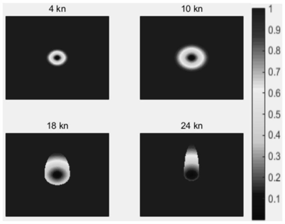
[0039] Step 3: Construct a dynamic obstacle model through the fast scanning method;

[0040] Step 4: Superimpose the potential field obtained in Step 2 and Step 3 to obtain the final planning potential field of the UAV;

[0041] Step 5: Use the gradient descent method to plan the navigation path of the unmanned vehicle i...

specific Embodiment approach 2

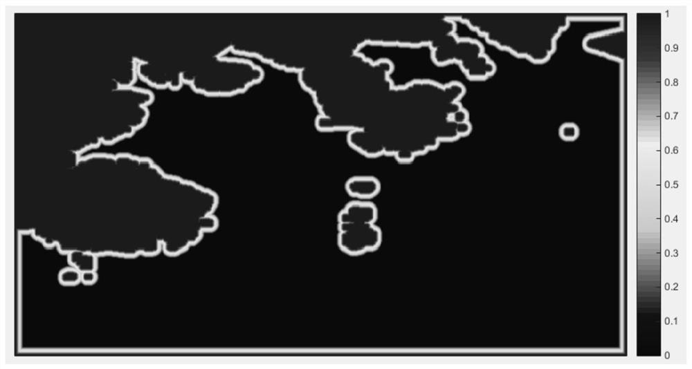
[0044] Specific implementation mode two: combination Figure 1 to Figure 8l Describe this embodiment. In step 1 of this embodiment, first transfer the task environment map to a grid map and process it into a binary map. 1 represents the static obstacle area, 0 represents the ocean area, and the coastline is extracted, that is, 0 , 1 The boundary is set as the scanning source point, and the FSM algorithm is used to scan the ocean area until the values ​​of all nodes converge, that is |t new -t old |≤δ, δ is the minimum value at which the given control iteration stops, t new is the updated value of the node, t old is the value before the update of the node, the normalized potential field, and the static environment map is generated after threshold value processing. The static environment remains unchanged throughout the planning process, and the generated map matrix is ​​recorded as M static and store. The undisclosed technical features in this embodiment are the same as tho...

specific Embodiment approach 3

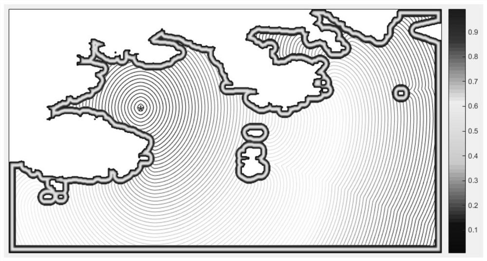
[0061] Specific implementation mode three: combination Figure 1 to Figure 8l Describe this implementation mode. In step 2 of this implementation mode, in M static Basically, the end point of the mission of the unmanned ship is set as the scanning source point, that is, the value of the end point is initialized to 0, and the static global situation field is obtained by using the fast scanning method, and the generated map matrix is ​​denoted as M PF . The undisclosed technical features in this embodiment are the same as those in the second embodiment.

[0062] In this embodiment, combined with figure 2 to explain, to figure 1 Using the fast scan method again, in the static environment matrix M static Based on the task end point as the initial point of scanning, FSM is used to obtain the static global situation field, and the generated map matrix is ​​denoted as M PF , is the final potential field used for static global path planning. Different from generating a static en...


PUM


Abstract

The invention discloses a path planning method for a surface unmanned boat based on a fast scanning method, which relates to the technical field of the surface unmanned boat. The invention aims to solve the problem that the traditional potential energy method is prone to produce local minimum values ​​when planning the path of the existing unmanned water surface craft. The invention includes obtaining global map information, constructing a static global environment potential field through a fast scanning method; obtaining the current unmanned boat state and surrounding obstacle information, and according to the mission requirements of the unmanned boat, constructing a map with the mission end point as the source point through a fast scanning method The potential field of the unmanned ship; the dynamic obstacle model is constructed by the fast scanning method; the potential field obtained in the step 2 and step 3 is superimposed to obtain the final planning potential field of the unmanned vehicle; the gradient descent method is used to plan the unmanned vehicle in the potential field in step 4 The sailing path of the boat; if the unmanned boat reaches the mission target point, the cycle ends; otherwise, go to step three. The invention is used for the route planning of the surface unmanned boat.

Description

technical field [0001] The invention relates to the technical field of surface unmanned boats, in particular to a path planning method for surface unmanned boats based on a fast scanning method. Background technique [0002] Unmanned Surface Vehicles (USV) is a new type of intelligent equipment. In recent years, due to its unmanned and intelligent characteristics, it has attracted people's attention and has been widely used in civilian and military fields. Path planning technology, as the key to autonomous decision-making technology of unmanned vehicles, is the basis of navigation and motion control of unmanned vehicles, and it is related to the intelligence level of unmanned vehicles to a certain extent. [0003] According to the degree of mastery of environmental information, the path planning of unmanned vehicles can be divided into global path planning based on global information and local path planning based on sensor information. [0004] Local path planning is a smal...

Claims


Application Information

Patent Timeline
Patent Type & Authority Patents(China)
IPC IPC(8): G05D1/02
CPCG05D1/0206
Inventor 庄佳园罗靖宋生清张磊苏玉民王博沈海龙曹建孙玉山朱骋周彬王建东
Owner HARBIN ENG UNIV
Why Eureka
Try Eureka