Quantifiable cutting device for factory aluminum profiles

A technology for cutting devices and aluminum profiles, which is applied in the direction of shearing devices, accessories of shearing machines, manufacturing tools, etc., can solve the problem of inconvenient adjustment of cutting angles for cutting devices, achieve the goals of saving adjustment time, convenient adjustment, and lower installation requirements Effect

Active Publication Date: 2020-09-18
江苏东台天腾铝业有限公司
View PDF6 Cites 3 Cited by
  • Summary
  • Abstract
  • Description
  • Claims
  • Application Information

AI Technical Summary

Problems solved by technology

[0006] The invention provides a quantifiable cutting device for factory aluminum profiles, which can solve the problem that the cutting device in the prior art is inconvenient to adjust the cutting angle

Method used


Image

  • Quantifiable cutting device for factory aluminum profiles
  • Quantifiable cutting device for factory aluminum profiles
  • Quantifiable cutting device for factory aluminum profiles

Examples


specific Embodiment 1

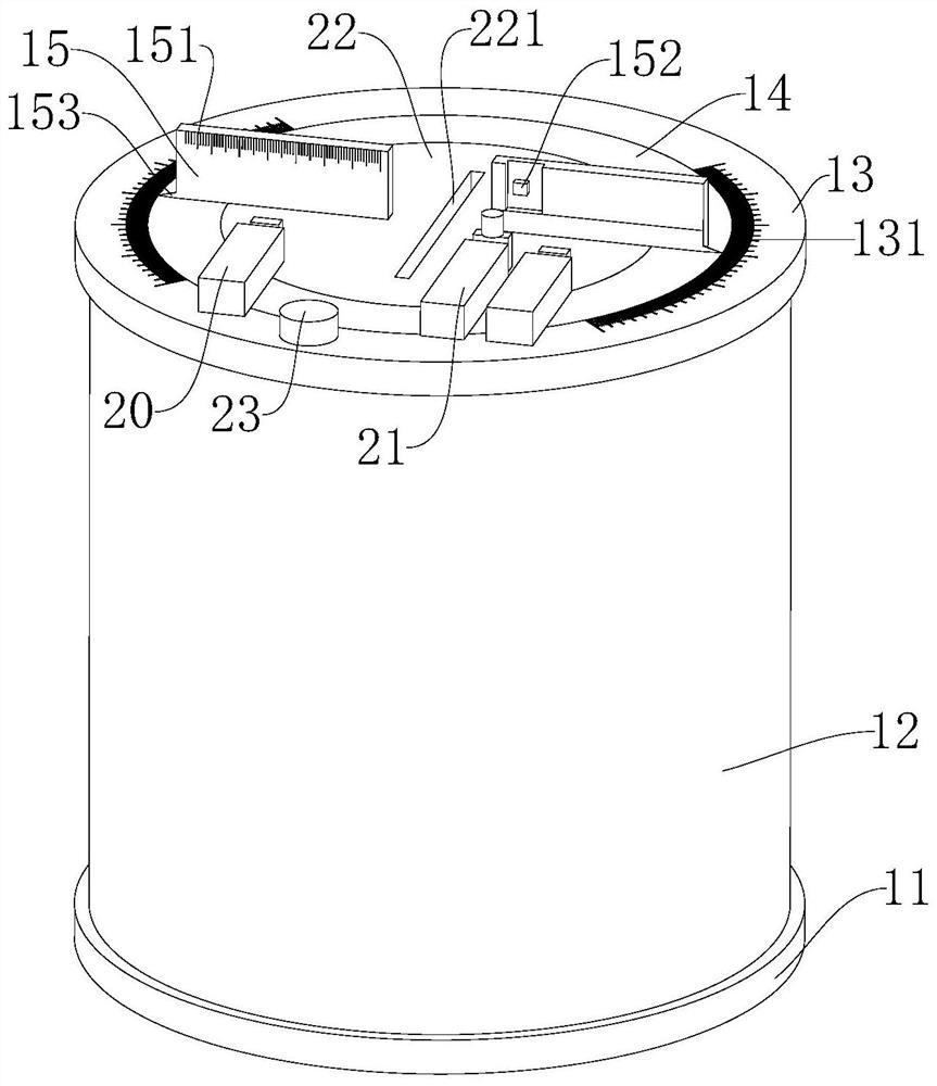
[0028] Such as Figure 1 to Figure 4 As shown, a quantitative cutting device for factory aluminum profiles provided by the embodiment of the present invention includes a body 1, a cutting device 2 and an adjusting device 32, wherein:

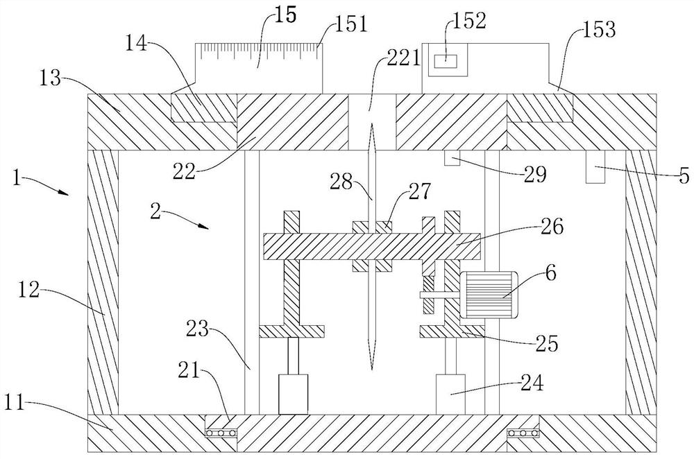
[0029] The body 1 comprises a base 11, a side wall 12, an upper support plate 13, a sliding ring plate 14 and a positioning plate 15, the upper end of the base 11 is fixedly connected with a side wall 12, and the upper end of the side wall 12 is fixedly connected with an upper support plate 13, and the upper support An annular chute is opened on the plate 13, and the sliding ring plate 14 is slidably arranged on the annular chute, the upper surface of the sliding ring plate 14 is flush with the upper surface of the upper supporting plate 13, and the two positioning plates 15 are respectively fixedly connected to the The different positions of the sliding ring plate 14, and the two positioning plates 15 are arranged on the same line, and the ends...

specific Embodiment 2

[0034] In Embodiment 1, since the actual structure of the cutting device 2 usually affects the adjustment of the cutting angle of the aluminum profile, in order to achieve better multi-angle cutting, on the basis of Embodiment 2, as Figure 1 to Figure 4 As shown, the end face bearing 4 is also included in this embodiment, and the cutting device 2 includes a lower pallet 21, an upper pallet 22, a support column 23, a first electric push rod 24, a support plate 25, a support shaft 26, a pressing block 27, Cutting sheet 28 and motor 6, lower supporting plate 21 is rotatably connected to base 11, and upper supporting plate 22 is rotatably connected in the give way groove, and the upper surface of upper supporting plate 22 is flush with the upper surface of upper support plate 13 , the outer circumference of the upper supporting plate 22 is provided with a fourth gear, the lower supporting plate 21 is fixedly connected with a number of supporting columns 23, the upper ends of the s...

specific Embodiment 3

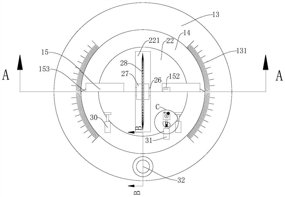
[0038] In embodiment 2, due to the fact that in actual use, large batches of processing are often required, the practicability of manually adjusting the cutting length is not strong, in order to realize automatic control of fixed-length feeding, so on the basis of embodiment 2, such as Figure 1 to Figure 5 As shown, this embodiment also includes a second electric push rod 30 and a feeding arm 31, the two second electric push rods 30 are fixedly connected to the sliding ring plate 14, and the two second electric push rods 30 correspond to two A positioning plate 15 is arranged, and the output shaft of the second electric push rod 30 points to the positioning plate 15, and the output shaft of the second electric push rod 30 is fixedly connected with a pressing plate, and the pressing plate is covered with rubber;

[0039] The feeding arm includes a third electric push rod 311, a push rod 312, a slide rod 313, a spring 314, a third button 315, a support shell 316, a servo motor 3...


PUM


Abstract

The invention discloses a quantifiable cutting device for factory aluminum profiles, and belongs to the field of machining equipment. The quantifiable cutting device is characterized in that a base isprovided with a side wall, the side wall is provided with an upper supporting plate, a sliding ring plate is slidably arranged on the upper supporting plate, positioning plates are connected to the sliding ring plate, the positioning plates are provided with pointers, the upper supporting plate is provided with angle scales, the positioning plates are provided with linear scales, a cutting devicebody is connected to the base, the upper supporting plate is provided with a receding groove, a rotary knob is connected to the upper supporting plate, a locking block is in threaded connection withthe rotary knob, the tooth number of a first gear is z1, the tooth number of a second gear is z2, the sliding ring plate is provided with a third gear, the tooth number of the third gear is z3, the cutting device body is provided with a fourth gear, the tooth number of the fourth gear is z4, and z1: z3 = z2: z4. According to the quantifiable cutting device, the rotary knob is adjusted, the first gear drives the sliding ring plate to rotate, and the cutting device body rotates reversely, so that adjustment is convenient, the installation requirement of equipment is lowered, then adjustment of the cutting angle is facilitated, quantitative cutting is achieved through the linear scales, and fixed-angle adjustment is achieved through cooperation of the angle scales and the pointers.

Description

technical field [0001] The invention relates to the field of mechanical processing equipment, in particular to a quantitative cutting device for aluminum profiles in factories. Background technique [0002] The aluminum profile is a long profile with a cross section extruded by a die. The user needs to process and cut the industrial aluminum profile into a suitable length according to his own needs before use. [0003] In the actual cutting process, the aluminum profile is most often cut along an angle of 0° or 45°, but with the popularity and development of the mechanical design industry, the application of non-standard parts is becoming more and more extensive. The cutting of aluminum profiles There are also many requirements for angle requirements, so the requirements for cutting machines are getting higher and higher. [0004] For the cutting machine in the prior art, there are two common methods for adjusting the cutting angle. One is to adjust the angle of the positio...

Claims


Application Information

Patent Timeline
Patent Type & Authority Applications(China)
IPC IPC(8): B23D19/00B23D33/00
CPCB23D19/00B23D33/00
Inventor 不公告发明人
Owner 江苏东台天腾铝业有限公司
Why Eureka
Try Eureka