
Laser welding machine capable of automatically rounding coiled tube motor stator

A laser welding machine, coil motor technology, applied in laser welding equipment, welding equipment, metal processing equipment and other directions, can solve the problems of not meeting the needs of large-scale production in factories and a large number of manual participation, saving manpower and improving work efficiency , to meet the effect of rotating needs

Active Publication Date: 2020-09-18
绍兴华熠智能设备股份有限公司 +2
View PDF8 Cites 9 Cited by
  • Summary
  • Abstract
  • Description
  • Claims
  • Application Information

AI Technical Summary

Problems solved by technology

[0003] The purpose of the present invention is to provide a laser welding machine for coil motor stators to automatically form circles in view of the fact that existing coil motor stator welding machines on the market require a large amount of manual participation and cannot meet the needs of large-scale production in factories. Fully automatic welding work

Method used


Image

  • Laser welding machine capable of automatically rounding coiled tube motor stator
  • Laser welding machine capable of automatically rounding coiled tube motor stator
  • Laser welding machine capable of automatically rounding coiled tube motor stator

Examples


Embodiment Construction

[0033] The present invention will be further described below in conjunction with the accompanying drawings.

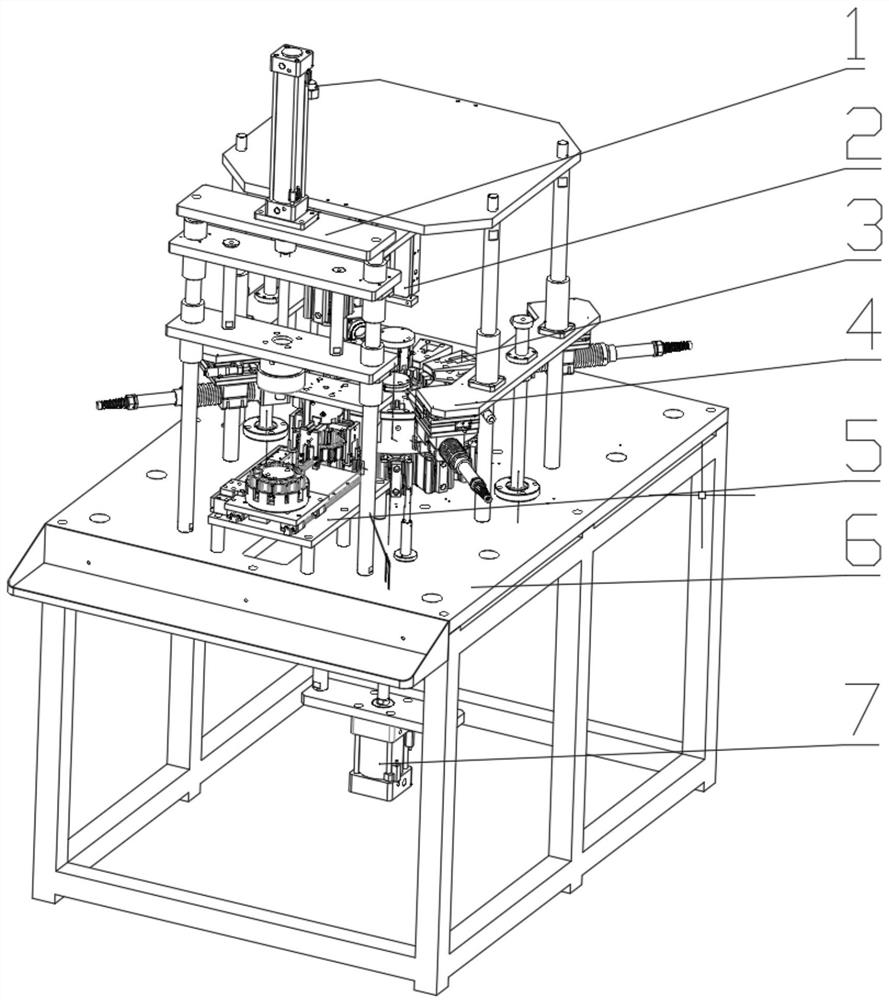
[0034] Such as figure 1 As shown, a laser welding machine for automatically forming a coil motor stator into a circle, including a pressing mechanism 1, a coil motor stator grasping mechanism 2, a clamping mechanism 3, a welding mechanism 4, a transmission mechanism 5, a frame 6 and a welding Fixture rotation mechanism 7.

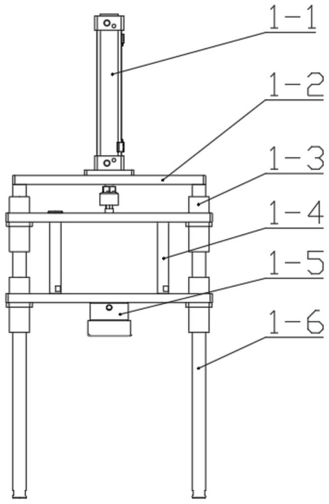
[0035] Such as figure 2 As shown, the pressing mechanism 1 includes a pressing cylinder 1-1, a pressing top plate 1-2, a pressing linear bearing 1-3, a pressing plate 1-4, a pressure head seat 1-5 and a pressing guide post 1-6 . The cylinder block of the pressing cylinder 1-1 is fixed on the pressing top plate 1-2; the upper ends of the two pressing guide posts 1-6 are fixed on the bottom surface of the pressing top plate 1-2, and the lower ends are all fixed on the frame 6; the lower pressing plate 1 The two ends of -4 and the two down-pressing ...


PUM


Abstract

The invention discloses a laser welding machine capable of automatically rounding a coiled tube motor stator. An existing coiled tube motor stator welding machine cannot meet large-scale production. The laser welding machine comprises a pressing mechanism, a coiled tube motor stator grabbing mechanism, a clamping mechanism, a welding mechanism, a transmission mechanism, a rack and a welding clamprotating mechanism, wherein the pressing mechanism returns after applying downward pressure to a coiled tube motor stator on the transmission mechanism; the transmission mechanism provides a pressed coiled tube motor stator to the coiled tube motor stator grabbing mechanism; the coiled tube motor stator grabbing mechanism grabs a coiled tube motor stator to be welded to the clamping mechanism, andunloads the welded coiled tube motor stator; the welding mechanism welds the coiled tube motor stator; and the welding clamp rotating mechanism realizes rotating the welding mechanism and enabling acentral core rear positioning shaft to extend into or withdraw from the welding mechanism. The laser welding machine can accomplish welding work of the coiled tube motor stator in a fully-automatic mode, and guarantees roundness of the coiled tube motor stator through an internal central core in a welding process.

Description

technical field [0001] The invention belongs to the field of welding equipment, and in particular relates to a laser welding machine for automatically rounding the stator of a coil motor. Background technique [0002] At present, in the field of welding technology, the welding work of the coil motor stator is mainly manual. Manual welding of the coil motor stator has low efficiency and is not conducive to large-scale production and processing. The existing coil motor stator welding machines on the market are all semi-automatic and still require manual participation. Therefore, it is necessary to design a fully automatic coil motor stator welding machine that can independently complete the welding work. Contents of the invention [0003] The purpose of the present invention is to provide a laser welding machine for coil motor stators to automatically form circles in view of the fact that existing coil motor stator welding machines on the market require a large amount of ma...

Claims


Application Information

Patent Timeline
Patent Type & Authority Applications(China)
IPC IPC(8): B23K26/21B23K26/70
CPCB23K26/21B23K26/702
Inventor 夏伟锋李晖姜亚东潘骏
Owner 绍兴华熠智能设备股份有限公司
Learn More