Ultrasonic grinding device

An ultrasonic and grinding technology, which is applied to the parts of grinding machine tools, grinding/polishing equipment, metal processing equipment, etc., can solve the problems of poor stability, loss, high failure rate, etc., and achieve the effect of improving the service life

Inactive Publication Date: 2020-09-18
JIANGXI AGRICULTURAL UNIVERSITY
View PDF6 Cites 1 Cited by
  • Summary
  • Abstract
  • Description
  • Claims
  • Application Information

AI Technical Summary

Problems solved by technology

However, the existing mechanical structural slip rings use carbon brushes to transmit electrical energy and other signals to relatively rotating devices. In this contact transmission mode, carbon brushes and copper rings will suffer serious losses during high-speed rotation, and the stability is relatively low. Poor, high failure rate

Method used


Image

  • Ultrasonic grinding device
  • Ultrasonic grinding device
  • Ultrasonic grinding device

Examples


Embodiment 1

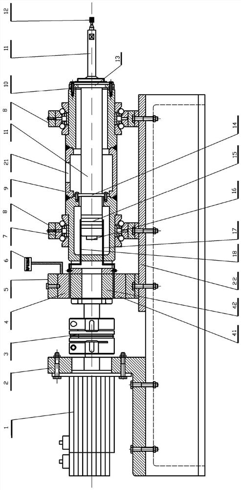
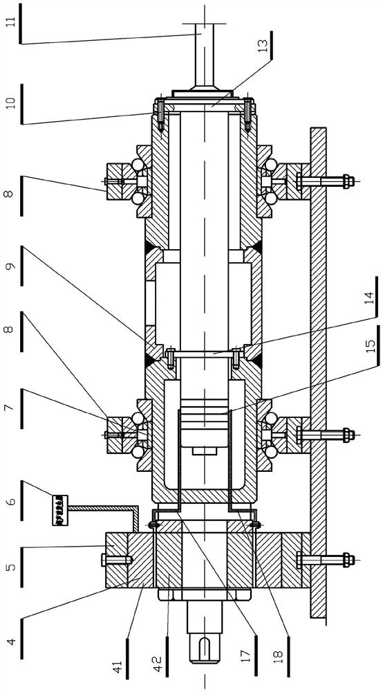
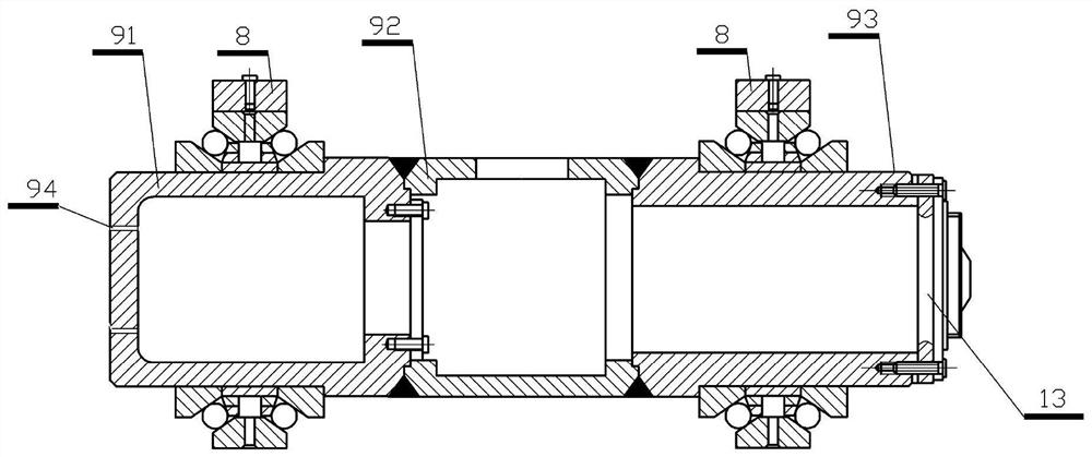
[0029] Example 1: An ultrasonic grinding device, see Figure 1 to Figure 5 .

[0030] It includes a motor base 2, a motor mounted on the motor base 2, a main shaft 9 with a tubular hollow structure, the main shaft 9 is mounted on the base 22 through two bearings 8 and can rotate through the bearings, and the main shaft 9 points There are three sections, namely the front section 93, the middle section 92 and the tail section 91 respectively. The front section 93, the middle section 92 and the tail section 91 are connected end to end in sequence. The bearing 8 is a bidirectional thrust angular contact ball bearing.

[0031] Further, the main shaft 9 is provided with an horn 11, the main shaft 9 is coaxially connected with the output shaft of the motor 1 through a coupling 3, and the main shaft 9 can be used by the output shaft of the motor 1 Driven to rotate, further, a transducer 15 is provided on the end of the horn 11 located in the main shaft 9 (this transducer is a prior art an...


PUM


Abstract

The invention provides an ultrasonic grinding device. By means of the ultrasonic grinding device, the structural design is novel, the service life of a brushless sliding ring on the ultrasonic grinding device is long, and meanwhile the vibration influence can be reduced. The ultrasonic grinding device comprises a motor seat, a motor mounted on the motor seat and a main shaft of a tubular hollow structure. The main shaft is mounted on the base through a bearing. An amplitude change rod is arranged in the main shaft, the main shaft is coaxially connected with an output shaft of the motor thougha coupling, and the main shaft can be driven by an output shaft of the motor to rotate. A transducer is arranged at the end of the amplitude change rod located in the mains haft, and two electrode connecting lines stretch out of the transducer. The main shaft is connected with the end of the main shaft driven by the coupling through the brushless sliding ring. Two electrode pieces extending out ofthe amplitude change rod are connected with an outer ultrasonic frequency power source through the brushless sliding ring.

Description

Technical field [0001] The invention relates to the technical field of ultrasonic grinding devices, in particular to an ultrasonic grinding device with a novel structure design and a brushless slip ring that provides an ultrasonic frequency power supply for an horn with a long service life. Background technique [0002] With people's exploration of the external environment and the progress of science and technology, the application and development of new materials are inseparable. For some of the particularities of the materials, traditional processing methods are no longer applicable, such as engineering ceramics, high-hardness metals and other hard and brittle materials that are difficult to process, especially non-metallic materials. These materials are now widely used in high-end mechanical equipment, aviation / aerospace engines, etc. However, these materials generally have the characteristics of poor grinding performance, high hardness and strength, harsh processing conditio...

Claims


Application Information

Patent Timeline
Patent Type & Authority Applications(China)
IPC IPC(8): B24B1/04B24B41/04B24B41/00
CPCB24B1/04B24B41/00B24B41/04
Inventor 杨卫平朱元俊付鹏何超
Owner JIANGXI AGRICULTURAL UNIVERSITY
Why Eureka
Try Eureka