Hanging bracket erected on construction platform constructed after building of highway bridge beam column tie beam

A technology of construction platform and bridge column, applied in bridge construction, bridge, bridge maintenance and other directions, can solve the problems of inability to realize new column-tie beam construction platform, limited construction height by hoop method, and difficult installation, etc., to achieve safe and reliable. The effect of turnover utilization, low cost and high tensile strength

Pending Publication Date: 2020-09-18
CCCC FOURTH HIGHWAY ENG
View PDF0 Cites 1 Cited by
  • Summary
  • Abstract
  • Description
  • Claims
  • Application Information

AI Technical Summary

Problems solved by technology

[0002] With the current traffic flow of existing highway bridges becoming increasingly saturated, the existing highway bridges cannot meet the needs of future traffic flow, so it is necessary to widen the existing highway bridges
According to the traditional construction technology, it is impossible to realize the construction platform where the newly added column beams are connected with the originally designed pier columns. The piercing rod method construction has no piercing holes reserved for the pier columns in the original design, and the hoop method is difficult to install due to the limited construction height. , great potential safety hazard during installation

Method used


Image

  • Hanging bracket erected on construction platform constructed after building of highway bridge beam column tie beam
  • Hanging bracket erected on construction platform constructed after building of highway bridge beam column tie beam
  • Hanging bracket erected on construction platform constructed after building of highway bridge beam column tie beam

Examples


Embodiment Construction

[0023] The following will clearly and completely describe the technical solutions in the embodiments of the present invention with reference to the accompanying drawings in the embodiments of the present invention. Obviously, the described embodiments are only some, not all, embodiments of the present invention. Based on the embodiments of the present invention, all other embodiments obtained by persons of ordinary skill in the art without creative efforts fall within the protection scope of the present invention.

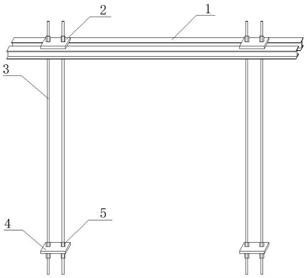
[0024] see figure 1 , the present invention provides a technical solution: a hanger erected on a construction platform constructed after the columns and beams of a highway bridge under construction, which is arranged on both sides of the top cover beam 6 of the existing pier column, including a top bracket 1 and a suspender 3. There are two sets of top brackets 1, two sets of top brackets 1 are respectively arranged on both sides of the boom 3, there are four sets ...


PUM


Abstract

The invention relates to the technical field of highway bridge beam column tie beam construction, in particular to a hanging bracket erected on a construction platform constructed after building of ahighway bridge beam column tie beam. The hanging bracket arranged on two sides of a capping beam on the top of an existing pier stud comprises a top brackets and suspenders, and the two sets of top brackets are arranged on the two sides of the suspenders correspondingly. Every two of the four groups of suspenders are arranged at two ends of the top brackets; a top plate is slidably connected to the upper ends of two adjacent groups of suspenders; and the lower ends of every two adjacent groups of suspenders are connected with a bottom plate in a sliding mode. The upper side and the lower sideof the top plate and the upper side and the lower side of the bottom plate are provided with two fastening nuts respectively. The fastening nuts are in threaded connection with the suspenders. A traditional lower compression system is converted into an upper tension system, the hanging bracket has the advantages of being small in dead weight, convenient to assemble and disassemble, low in cost, safe, reliable and convenient to recycle, and a problem that an existing construction platform for newly-added column tie beams under bent caps cannot be erected because center penetrating holes are notreserved and inner hoops with the limited height are difficult to install is effectively solved.

Description

technical field [0001] The invention relates to the technical field of highway bridge column system beam construction, in particular to a hanger erected on a construction platform constructed after highway bridge column system beam construction. Background technique [0002] With the current traffic flow of existing highway bridges becoming increasingly saturated, the existing highway bridges cannot meet the needs of future traffic flow, so it is necessary to widen the existing highway bridges. According to the traditional construction technology, it is impossible to realize the construction platform where the newly added column beams are connected with the originally designed pier columns. The piercing rod method construction has no piercing holes reserved for the pier columns in the original design, and the hoop method is difficult to install due to the limited construction height. , There is a great potential safety hazard during installation. [0003] In view of the abo...

Claims


Application Information

Patent Timeline
Patent Type & Authority Applications(China)
IPC IPC(8): E01D22/00E01D21/00
CPCE01D21/00E01D22/00
Inventor 孙茂辉鲁成辉张旭洋张炜许亮亮戚光久刘俊奇万艳彬刘万杰李鋆
Owner CCCC FOURTH HIGHWAY ENG
Why Eureka
Try Eureka