Optical fiber vibration measurement device and method with light source frequency shift calibration auxiliary channel

An auxiliary channel and optical fiber vibration technology, applied in the direction of measuring devices, measuring ultrasonic/sonic/infrasonic waves, instruments, etc., can solve the problems of reducing the phase noise of lasers, and it is difficult to further improve the measurement accuracy of external vibration signals, so as to improve measurement accuracy and improve Measurement accuracy, effect of eliminating phase noise

Pending Publication Date: 2020-09-18
珠海任驰光电科技有限公司
View PDF5 Cites 7 Cited by
  • Summary
  • Abstract
  • Description
  • Claims
  • Application Information

AI Technical Summary

Problems solved by technology

On the one hand, it is possible to improve the frequency stability of the light wave and reduce the phase noise by improving the laser material, keeping the ambient temperature, humidity, and atmospheric pressure stable; however, based on the existing laser manufacturing process and constant temperature, humidity, and pressure processing technology, significant Progress is not a technical method that is easy to achieve in the short term; on the other hand, the adverse effects of optical wave phase noise on vibration measurement accuracy and spatial positioning can be suppressed by designing new optical path structures and data processing methods. For digital signal processing methods, For example, based on the second difference The measurement method will be restricted by the effective bit (quantization noise) of the data acquisition card, which is only a digital signal processing method and does not fundamentally reduce the phase noise of the laser, and it is difficult to further improve the measurement accuracy of the external vibration signal

Method used


Image

  • Optical fiber vibration measurement device and method with light source frequency shift calibration auxiliary channel
  • Optical fiber vibration measurement device and method with light source frequency shift calibration auxiliary channel
  • Optical fiber vibration measurement device and method with light source frequency shift calibration auxiliary channel

Examples


Embodiment 1

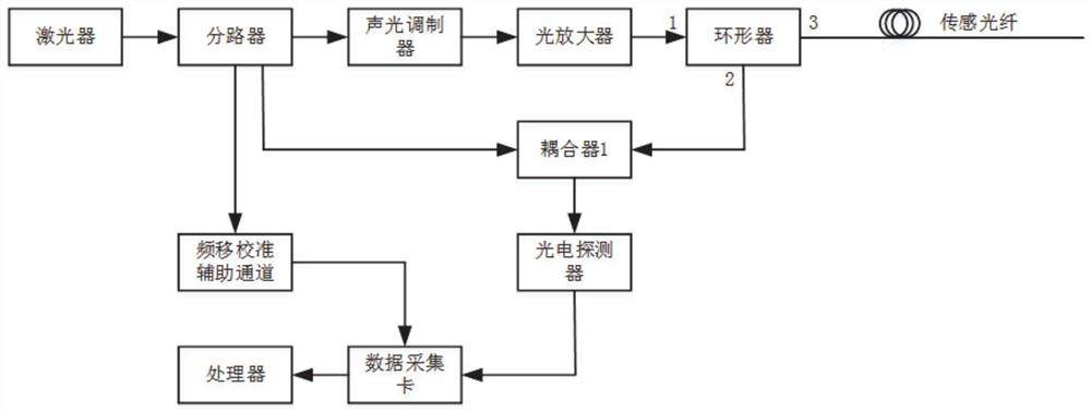
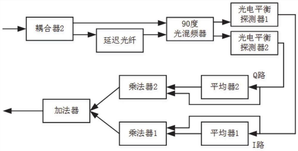
[0045] In a typical implementation of the present disclosure, such as Figure 1-Figure 2 As shown, a fiber optic vibration measurement device with an auxiliary channel for frequency shift calibration of the light source is proposed.

[0046] The device includes: laser, splitter, acousto-optic modulator, optical amplifier, circulator, sensing fiber, coupler 1, photodetector 1, frequency shift calibration auxiliary channel, photodetector 2, data acquisition card and processing device.

[0047] The laser emits narrow-linewidth continuous light, which is divided into 3 paths through a splitter, of which 1 path of continuous light passes through an acousto-optic modulator with a frequency shift function, converts it into pulsed light with a specific width and period, and then passes through an optical amplifier for power conversion. After compensation, it enters the 1 port of the circulator, and then enters the sensing fiber through the 3 port of the circulator, and obtains the vi...

Embodiment 2

[0055] In another typical embodiment of the present disclosure, as Figure 1-Figure 2 As shown, a fiber vibration measurement method with an auxiliary channel for frequency shift calibration of the light source is proposed.

[0056] Include the following steps:

[0057] The laser outputs continuous light with frequency v 0 +Δv 0 (t), v 0 Represents the ideal value of the light wave frequency, which is a constant, but due to the inevitable noise of the laser, the light wave frequency contains a frequency drift component Δv 0 (t), t represents time;

[0058] The continuous light of the laser is divided into 3 paths through the splitter, and the first path of continuous light passes through the acousto-optic modulator with frequency shift function, converts it into pulsed light with a specific width and period, and then enters the sensor through the optical amplifier and circulator. Optical fiber to obtain Rayleigh scattered light wave E r (z i , t), z i Indicates the pos...


PUM


Abstract

The invention provides an optical fiber vibration measurement device and method with a light source frequency shift calibration auxiliary channel. The invention relates to the field of optical fiber distributed vibration measurement. In a traditional phase-sensitive optical time domain reflection measurement device, a frequency shift calibration auxiliary channel is added as an auxiliary channel of the measurement device to completely compensate frequency drift of a light source and eliminate phase noise of a laser. In a feed-forward loop of a light source noise suppression feed-forward structure, two paths of mutually orthogonal interference light signals are obtained based on an interferometer and a 90-degree optical mixer, respectively output to a photoelectric balance detector 1 and aphotoelectric balance detector 2, and converted into two paths of interference electric signals. The influence of random change of an optical frequency initial phase on a measurement result when the optical frequency drift amount is measured based on a single signal is avoided, and the measurement precision of an external vibration signal is improved.

Description

technical field [0001] The present disclosure relates to the field of optical fiber distributed vibration measurement, in particular to an optical fiber vibration measurement device and method with an auxiliary channel for frequency shift calibration of a light source. Background technique [0002] The statements in this section merely provide background information related to the present disclosure and may not necessarily constitute prior art. [0003] Optical time domain reflectometry technology is based on the backscattering of light and Fresnel's reverse principle, using the backscattered light waves generated when pulsed light waves propagate in optical fibers to obtain information on energy (amplitude) attenuation, which can be used to measure optical fiber attenuation , connector loss, optical fiber fault point location, and understanding the loss distribution of optical fiber along the length, etc., are indispensable technologies in optical cable construction, mainte...

Claims


Application Information

Patent Timeline
Patent Type & Authority Applications(China)
IPC IPC(8): G01H9/00
CPCG01H9/004
Inventor 于淼王忠民常天英杨先勇崔洪亮杨先进郑志丰程立耀吴崇坚张耀鲁
Owner 珠海任驰光电科技有限公司
Why Eureka
Try Eureka