Assembling tool of high-voltage switch equipment
A high-voltage switch and assembly tooling technology, which is applied to switchgear, electrical components, etc., can solve the problems of high labor intensity of workers and low production efficiency of high-voltage switchgear, and achieve the effect of simple structure, easy implementation, and improved structural stability
- Summary
- Abstract
- Description
- Claims
- Application Information
AI Technical Summary
Problems solved by technology
Method used
Image
Examples
specific Embodiment 1
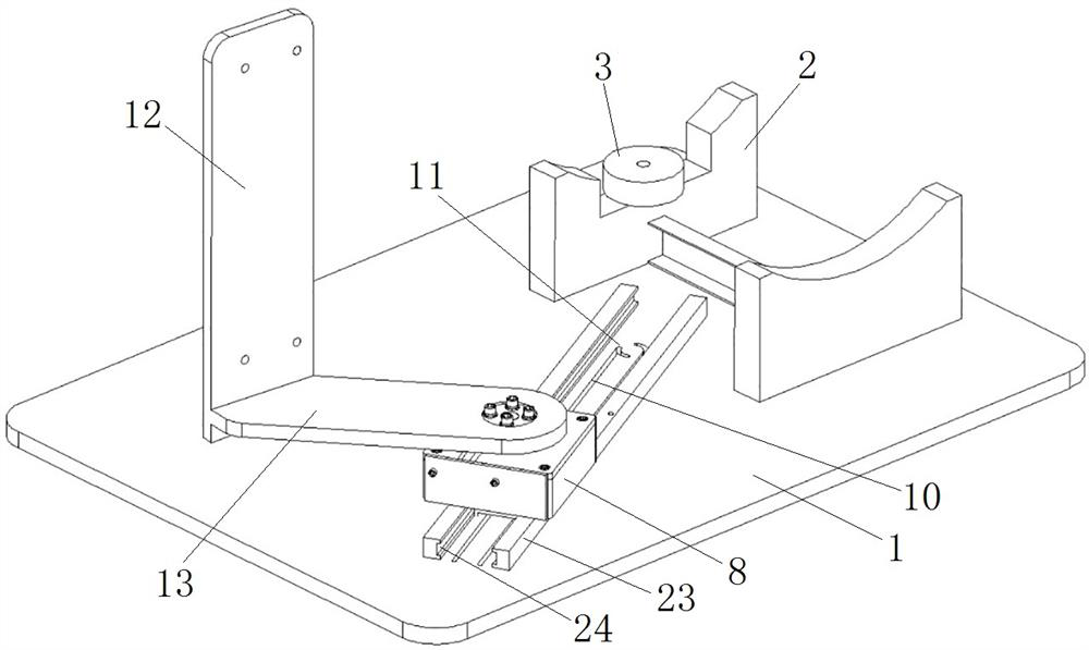
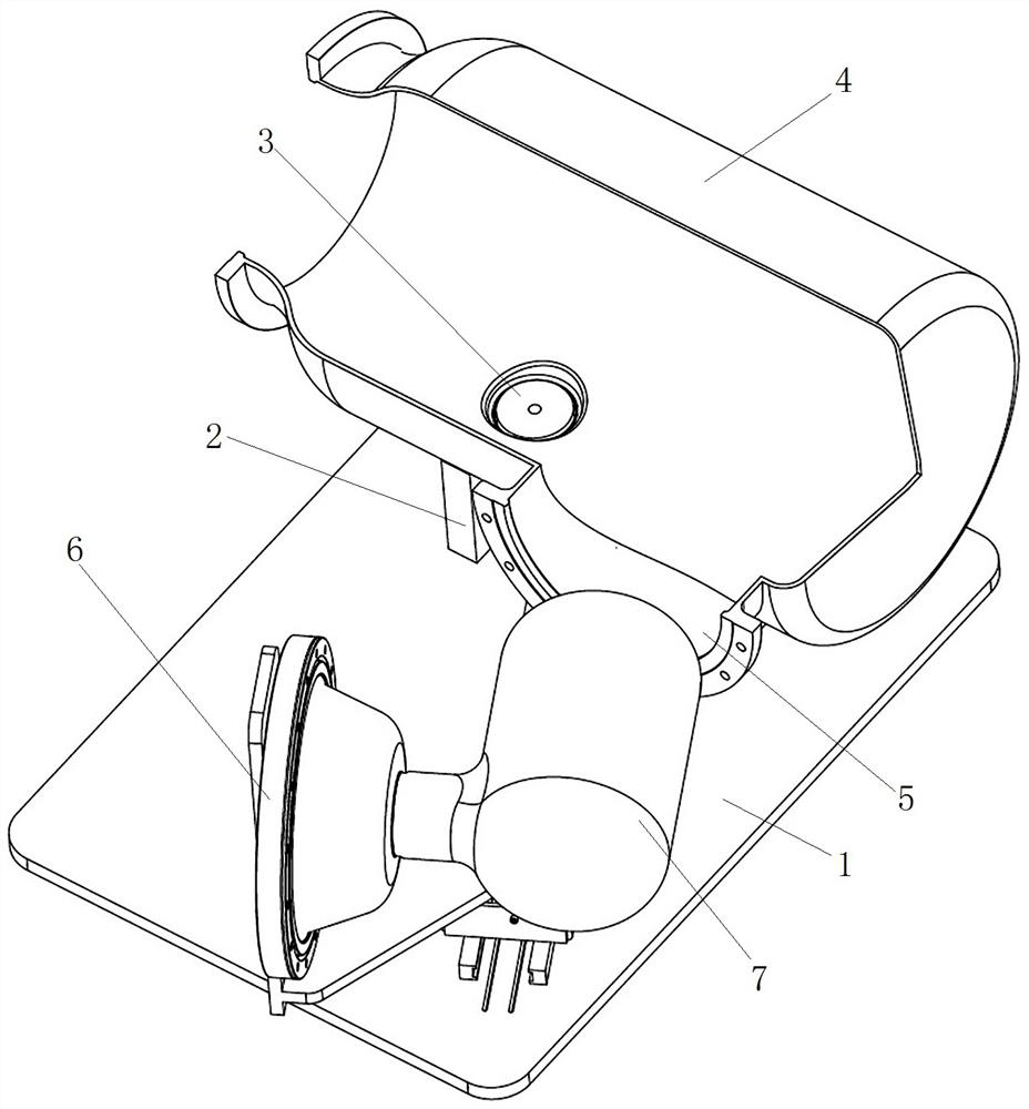
[0038] The assembly tooling of the medium and high voltage switchgear of the present invention is used to realize the assembly of the pre-assembled parts of the insulator 6 and the central conductor 7 and the barrel 4 in the miniaturized isolating earthing switch. Since the overall volume of the miniaturized isolating and grounding switch is reduced, the working space available for assembly operation in the cylinder 4 is reduced accordingly, and the insulator 6 and the central conductor 7 that make up the isolating and grounding switch need to be assembled outside the cylinder 4 to form a pre-assembled Parts, and then the pre-assembled parts are assembled to the inside of the cylinder 4. The assembly tool of the high-voltage switchgear in this embodiment is used to assemble the pre-assembled components into the cylinder body 4 .
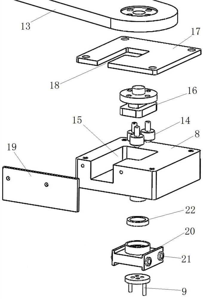
[0039] Such as figure 1As shown, the assembly tooling of the high-voltage switchgear (hereinafter referred to as the assembly tooling) includes a b...
specific Embodiment 2
[0052]The difference between it and the specific embodiment 1 is that no moving seat is set in the assembly tool, no roller track is set on the base, and a universal wheel is set on the bottom of the mounting seat body, and the universal wheel forms a guide rail matching part, and the corresponding guide rail serves as a guide The guide rail includes a guide section and a rotation section. The guide section is a guide section, and the rotation section is an arc section. The opening is upward and the mouth is small and the belly is big. The end of the guide groove section of the guide groove has an opening set along the direction of the guide groove section. The universal wheel can enter the guide groove along the opening and pass through the mouth of the guide groove. The large structure restricts the universal wheel from deviating from the guide groove. The universal wheels play a supporting and guiding role. When the mounting base moves along the guide rail, the universal wh...
specific Embodiment 3
[0054] The difference from the specific embodiment 1 is that the guide rail is a guide protrusion, the rotating section is an arc-shaped guide protrusion, the guide section is a guide protrusion, and the guide rail matching part on the corresponding mounting base is a guide rail arranged at the bottom of the mounting base body The mating block, the guide rail mating block is provided with a guide groove adapted to the corresponding guide protrusion. When the installation seat moves along the guide rail, the guide protrusion and the guide groove slide and fit.
PUM
 Abstract
Description
Claims
Application Information
 - R&D
- Intellectual Property
- Life Sciences
- Materials
- Tech Scout
- Unparalleled Data Quality
- Higher Quality Content
- 60% Fewer Hallucinations
Browse by: Latest US Patents, China's latest patents, Technical Efficacy Thesaurus, Application Domain, Technology Topic, Popular Technical Reports.
© 2025 PatSnap. All rights reserved.Legal|Privacy policy|Modern Slavery Act Transparency Statement|Sitemap|About US| Contact US: help@patsnap.com


