
Single-rotor disc applied to disc type motor

A disk motor and single rotor technology, which is applied in the direction of electrical components, electromechanical devices, electric components, etc., can solve the problems affecting the compactness of the rotor disk structure, large cage margin, difficult production and processing, etc., and achieve the requirement of reducing positioning accuracy , Improving the compactness of the structure and good consistency

Active Publication Date: 2020-09-18
HANGZHOU ZONHOW ELECTRIC TECH CO LTD
View PDF5 Cites 3 Cited by
  • Summary
  • Abstract
  • Description
  • Claims
  • Application Information

AI Technical Summary

Problems solved by technology

The disadvantage of the existing technology is that the magnetic steel is pressed and fixed by the cage, and the cage needs positioning points at the positions corresponding to the magnetic steel. There are too many positioning points, the fault tolerance rate is low, and very high positioning accuracy is required during installation. Production It is not easy to process. If the demand for positioning accuracy is reduced, the margin required for the cage will be large, which will affect the accuracy of the device after forming and affect the structural compactness of the rotor disk.

Method used


Image

  • Single-rotor disc applied to disc type motor
  • Single-rotor disc applied to disc type motor
  • Single-rotor disc applied to disc type motor

Examples


Embodiment 1

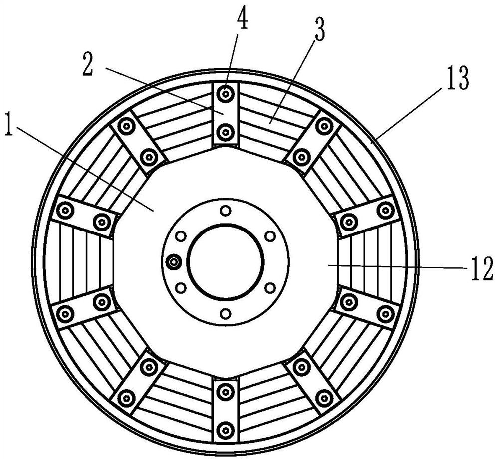
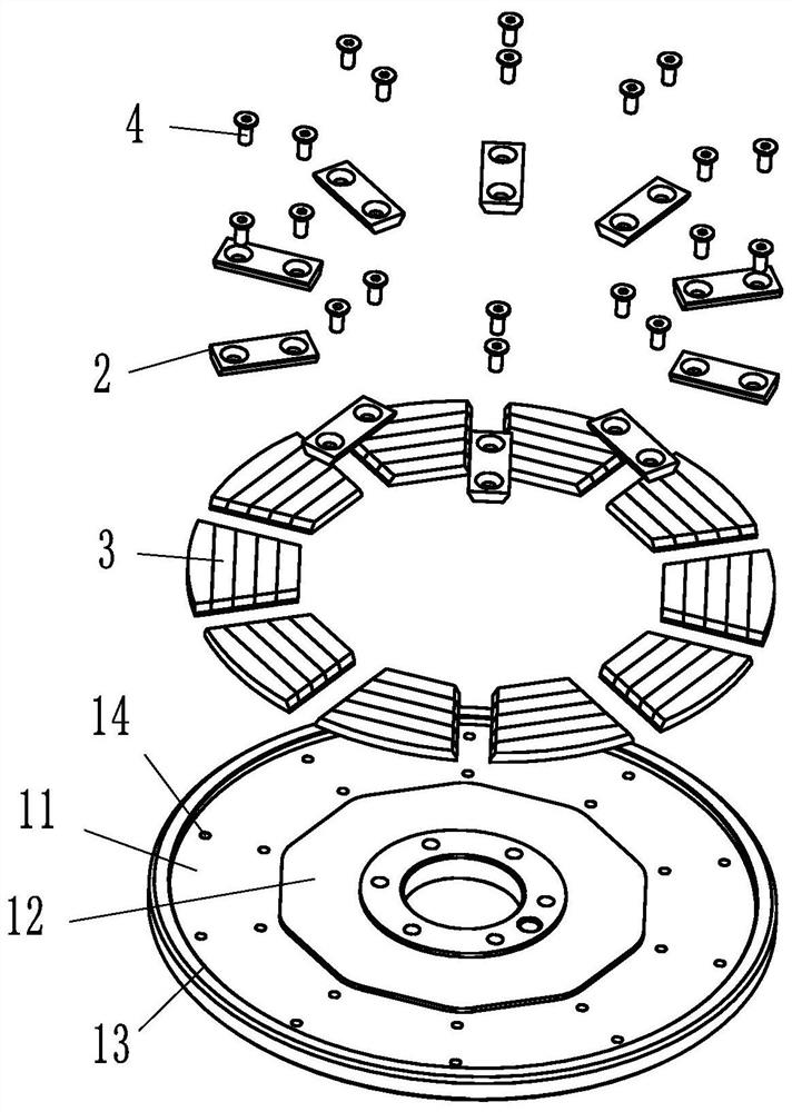
[0027] like Figures 1 to 4 As shown, it is a single-rotor disk applied to a disk motor, including a mounting disk 1, an annular mounting groove 11 is provided inside the mounting disk 1, and an upwardly protruding annular flange is provided on the inner and outer edges of the mounting groove 11 The shape of the inner ring 12 of the installation groove 11 is a regular polygon, and the shape of the outer ring 13 of the installation groove 11 is a circle. The mounting groove 11 can be directly formed by milling a cylinder. The mounting plate 1 is provided with ten sets of mounting holes 14 distributed in a circular array, the mounting holes 14 are located in the mounting groove 11 and the array axis of the ten sets of mounting holes 14 is the axis of the mounting plate 1 . Each set of mounting holes 14 is provided with aligned magnetic steel pressure blocks 2 , and a single set of mounting holes 14 includes two threaded holes, and the two threaded holes are located in the radia...

Embodiment 2

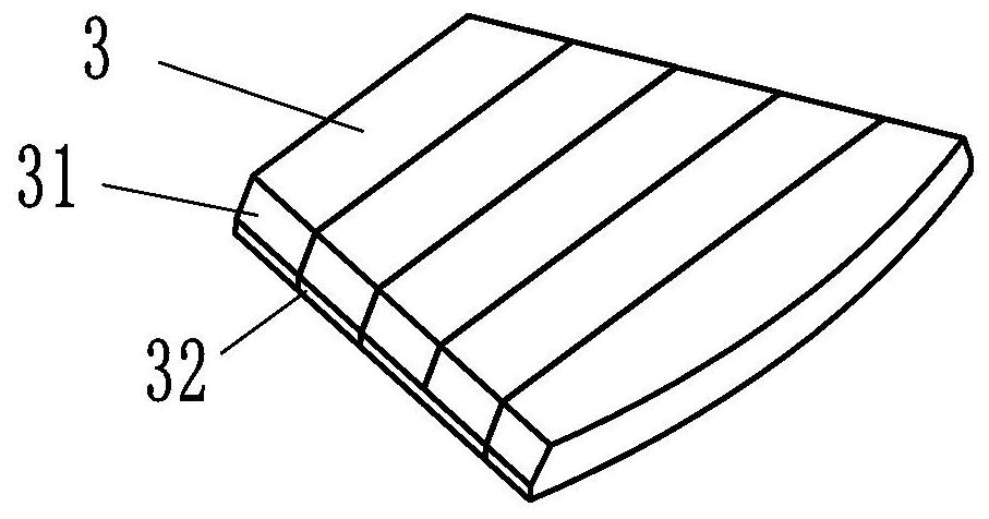
[0029] like Figure 5 As shown, the difference between embodiment 2 and embodiment 1 is that the pressing surface 21 is a bent stepped surface. Therefore, the mating surface 31 is a stepped surface mated with the pressing surface 21 . After the steel briquetting block and the magnetic steel 3 are mated, the matching accuracy of the end faces is low. Even if there is a processing error, the magnetic steel 3 will not move in the magnetic steel briquetting block 2, which is more convenient for assembly and has high stability.

Embodiment 3

[0031] like Figure 6 As shown, the difference between Embodiment 3 and Embodiment 1 lies in that four protruding rack pieces 22 are arranged in the pressing surface 21 . The rack plate 22 is a strip-shaped sheet structure, and the four rack plates 22 are equal and arranged in parallel, and the rack plates 22 are parallel to the bottom side of the magnetic steel pressing block 2; the adjacent rack plates 22 are on the pressing surface 21 The distance above is equal to the width of the rack plate 22. The rack piece 22 forms an outwardly convex elastic structure, which can be made of softer material than the magnetic steel. When there is a gap between the magnetic steel briquetting block 2 and the magnetic steel 3 due to processing errors, the rack piece 22 is bent to fill the pressure. The gap between the tight surface and the matching surface can assist the compression of the magnetic steel briquetting block 2 .


PUM


Abstract

The invention discloses a single-rotor disc applied to a disc type motor, and the disc comprises a mounting disc, a plurality of groups of mounting holes distributed in a circumferential array are formed in the mounting disc, each group of mounting holes is provided with aligned magnetic steel pressing blocks, and magnetic steel is arranged between the adjacent magnetic steel pressing blocks; pressing faces are arranged on the two sides of the magnetic steel pressing block respectively, and matching faces capable of being matched with the pressing faces are arranged on the two sides of the magnetic steel respectively. The single-rotor disc has the advantages that the magnetic steel support is converted into the magnetic steel pressing blocks, the positioning precision between the magneticsteel pressing blocks is not related, over-positioning cannot be formed, and therefore the precision requirement needed by magnetic steel assembling can be lowered, the magnetic steel pressing blockspress the magnetic steel, the assembling stability and assembling precision of the magnetic steel are guaranteed, and the installing efficiency of the single-rotor disc is improved; compared with a traditional rotor disc structure in which magnetic steel is installed by stamping groove positions in an installation disc, the installation disc can directly mill the installation grooves in a millingmode, and machining is more convenient.

Description

technical field [0001] The invention belongs to the field of disc motors, in particular to a single rotor disc applied to disc motors. Background technique [0002] Disc motor, also known as disc motor, has the characteristics of small size, light weight and high efficiency. Generally, the rotor and stator of the motor are set inside and outside. The shape of the disc motor is thin. The stator adopts a flat base plate. Magnet magnets or rotor discs with permanent magnet magnets glued on. The existing assembled rotor disc structure has many problems. [0003] For example, the Chinese patent document CN208158266U disclosed on November 27, 2018 "the fixed structure of the magnetic steel in the rotor assembly of the disc motor", including the rotor disc, a number of magnetic steels, and a cage. The surface of the rotor disc is provided with an annular groove. The outer ring of the groove is provided with gaps at intervals, and several magnetic steels are arranged in the annula...

Claims


Application Information

Patent Timeline
IPC IPC(8): H02K1/27H02K1/32
CPCH02K1/2793H02K1/32H02K2201/12
Inventor 徐鹏张国强陈栋尤壤
Owner HANGZHOU ZONHOW ELECTRIC TECH CO LTD
Learn More