Vacuum transfer assembly

A component and vacuum technology, applied in the field of vacuum transfer components, can solve problems such as loss of resolution, icing of brackets, and no new possibility of vacuum transfer brackets, etc., and achieve the effect of reduced vibration sensitivity and good resolution

Active Publication Date: 2020-09-18
HENNYZ BV
View PDF16 Cites 2 Cited by
  • Summary
  • Abstract
  • Description
  • Claims
  • Application Information

AI Technical Summary

Problems solved by technology

Insertion through air has a number of disadvantages: a) the vacuum in the TEM is poor; b) air-sensitive samples cannot be inserted easily; c) cryo-transfer of cryogenic samples is complicated and knots always occur on the tip of the holder. ice
This has the disadvantage that the rod on which the sample is placed has a smaller diameter, since it must fit inside the second airlock, and a further disadvantage is that the second airlock adds to the actual length of the goniometer / stand combination, This may result in a loss of resolution
The small diameter of the rod on which the sample is placed limits the possibility of sample cooling and severely increases the possibility of in situ stimulation such as biasing tools
The document does not address new possibilities for the functionality of existing vacuum transfer holders

Method used


Image

  • Vacuum transfer assembly
  • Vacuum transfer assembly
  • Vacuum transfer assembly

Examples


Embodiment Construction

[0035] In a first aspect, the invention relates to a vacuum transfer assembly according to aspect 1 .

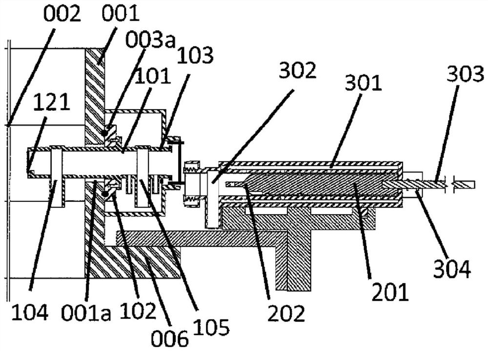
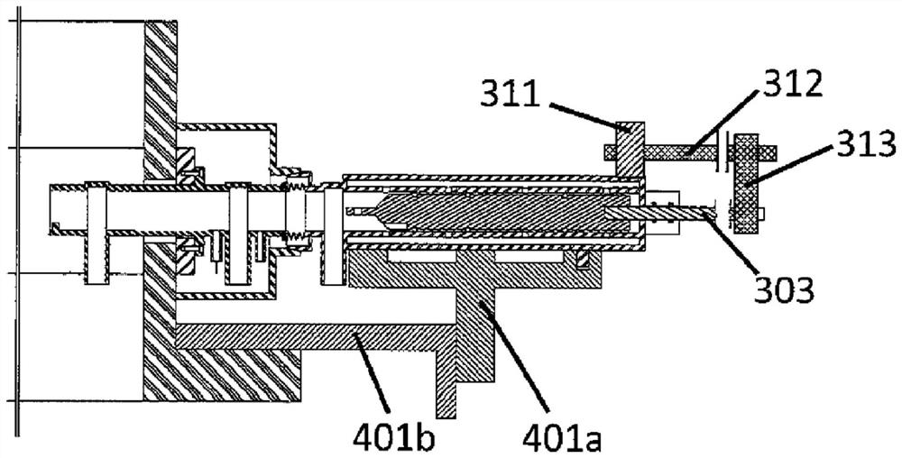
[0036] In an exemplary embodiment, the present assembly may include a loading rod 303 that is connected to the sample holder 201 to allow controlled loading of the sample holder to its final position in the TEM and vice versa, which may be computer controlled.

[0037] In an exemplary embodiment of this assembly, at least one length of the vacuum housing may be greater than the length of the outer tube, the vacuum housing valve may be located at the first end of the vacuum housing, and wherein, at the other end of the vacuum housing, a There is a narrow section including a fourth seal 304 that provides a passage for either the loading rod or the insertion rod.

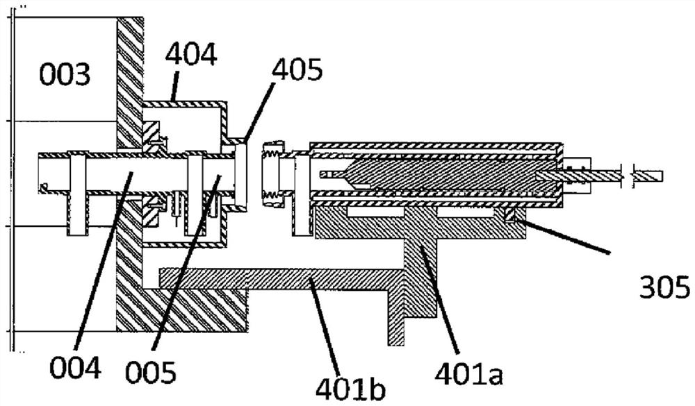
[0038]This assembly includes at least one of a holder 405 for attachment to the lens barrel 001 of the microscope, a holder 121, and a wave portion for fixing the alignment portion of the vacuum housing 310 to the TE...


PUM


Abstract

The present invention is in the field of a vacuum transfer assembly, such as for cryotransfer, and specifically a TEM vacuum transfer assembly, which can be used in microscopy, a sample holder, a vacuum housing, a sample holder stage and a sample holder coupling unit for use in the assembly, and a microscope comprising said assembly as well as a method of vacuum transfer into a microscope.

Description

technical field [0001] The present invention relates to the field of vacuum transfer assemblies, such as vacuum transfer assemblies for cryogenic transfers and in particular to TEM vacuum transfer assemblies, which can be used in microscopes, sample holders, vacuum housings, sample holder stages, and samples for such assemblies A bracket connection unit, and relates to a microscope including the assembly, and a method for vacuum transfer into the microscope. Background technique [0002] The present invention relates to the field of microscopes, in particular to the fields of electron microscopes and focused ion beam microscopes (EM and FIB), in particular to the field of transmission electron microscopes (TEM). However, its application can in principle be extended to any area of ​​microscopy, especially where the specimen (or sample) has cooled or needs to be cooled or the ingress of air has to be prevented. [0003] Microscopy is a technique frequently used in scientific ...

Claims


Application Information

Patent Timeline
Patent Type & Authority Applications(China)
IPC IPC(8): H01J37/20
CPCH01J37/20H01J2237/2001H01J2237/2004H01J2237/204H01J2237/2802G02B21/32
Inventor H·W·赞德伯格
Owner HENNYZ BV
Why Eureka
Try Eureka