Double-stage ultrafine pulverizer

An ultra-fine pulverizer and coarse pulverizing technology, applied in grain processing and other directions, can solve the problems of poor pulverization particle size uniformity, large total energy consumption, large wear of hammer and ring gear, etc., to increase the pulverizing area and reduce the total energy. The effect of reducing consumption and total cost

Active Publication Date: 2020-09-22
FAMSUN CO LTD
View PDF24 Cites 0 Cited by
  • Summary
  • Abstract
  • Description
  • Claims
  • Application Information

AI Technical Summary

Problems solved by technology

The secondary crushing process has the disadvantages of high cost of purchasing other equipment, large total energy consumption, large floor area, and is not suitable for small feed mills.
[0004] 1. The pulverization time of the superfine pulverizer is long, the energy consumption is high, and the uniformity of the pulverization particle size is poor;
[0005] 2. Poor crushing effect on coarse fiber materials;
[0006] 3. The hammer knife and ring gear of the ultrafine powder are greatly worn

Method used


Image

  • Double-stage ultrafine pulverizer
  • Double-stage ultrafine pulverizer
  • Double-stage ultrafine pulverizer

Examples


Embodiment 1

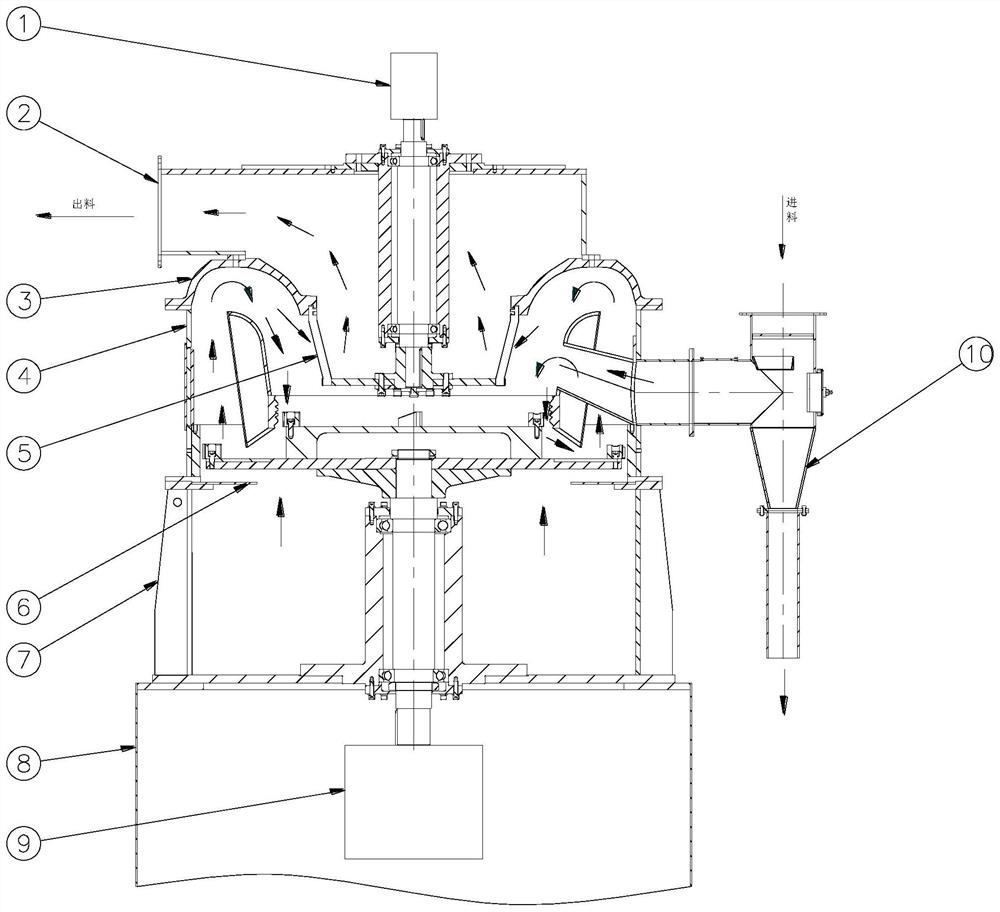
[0042] Such as figure 1 , 2 As shown, a two-stage ultrafine pulverizer includes a discharge chamber 2, a crushing system 4, an air transportation system, a classification system 5, a bottom bracket 8, and a feeding pipe 10.

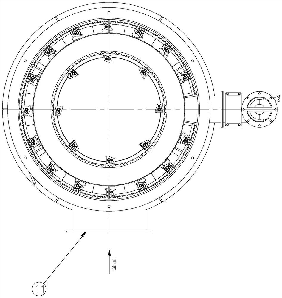
[0043] The top of the bottom bracket 8 is equipped with a clean air chamber 7, the air inlet 11 is located on the side of the clean air chamber 7, the top of the clean air chamber 7 is equipped with an assembled liner 6, and the top of the clean air chamber 7 is connected to the crushing system 4. The air purification chamber 7 and the air inlet 11 form a wind transportation system for material transportation between the crushing system 4 and the discharge chamber 2 . Assembled liner 6 is a circular ring as a whole, and is divided into six pieces, which are installed on the flange below the crushing system 4 through bolts, and can be disassembled and assembled through the inspection door of the purified air chamber 7 for easy replacement.

[0044] Such ...

Embodiment 2

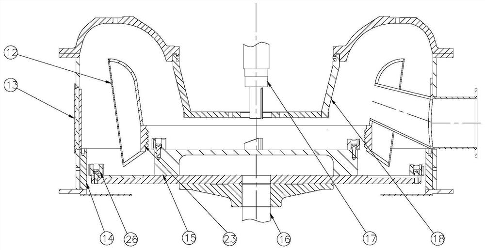
[0057] The difference from Embodiment 1 is that the structure of the shunt hood 12 is different, and the shunt shroud 12 is a single-layer conical shroud structure. The lower part of the inner wall of the shunt cover 12 is provided with a coarse crushing ring gear 30 .

Embodiment 3

[0059] Such as Figure 10 As shown, the difference from Embodiment 1 is that the installation positions of the coarse crushing ring gear and the coarse crushing hammer knife 30 are different, the material movement track is different, the structure of the shunt cover 12 is different, and the structure of the feed pipe 10 is different.

[0060] The number of coarse crushing ring gears is two, including the first coarse crushing ring gear 37 and the second coarse crushing ring gear 38, which are arranged oppositely. The first coarse crushing ring gear 37 is arranged on the inner wall of the crushing system, and the second coarse crushing ring gear 38 It is arranged on the outer wall of the shunt cover 12.

[0061] The fine crushing ring gear 14 is arranged on the inner wall of the crushing system.

[0062] The hammer knife mounting plate comprises a crushing support plate 28, a crushing chassis 27, and the crushing support plate 28 is installed on the top of the crushing system ...


PUM


Abstract

The invention belongs to the technical field of pulverizing equipment, and particularly discloses a double-stage ultrafine pulverizer. The double-stage ultrafine pulverizer comprises a discharging chamber, a pulverizing system and an air conveying system. A grading system is arranged in the discharging chamber. A feeding pipe is arranged on the pulverizing system. The air conveying system is usedfor conveying materials of the pulverizing system and the discharging chamber. The double-stage ultrafine pulverizer is characterized in that the pulverizing system comprises a flow separation cover,a coarse pulverizing device and a fine pulverizing device. The coarse pulverizing device and the fine pulverizing device are arranged in sequence in the material movement direction. By the adoption ofthe double-stage ultrafine pulverizer, the purpose that the requirement of the target particle size can be met by the primary pulverizing technology of only one vertical type ultrafine pulverizer isachieved, the pulverizing efficiency is improved, the good pulverizing effect on rough materials can also be achieved, the total energy consumption and the total cost of the conventional secondary pulverizing technology are reduced, and the double-stage ultrafine pulverizer has the broad application prospect.

Description

technical field [0001] The invention relates to the technical field of pulverizing machinery and equipment, in particular to a two-stage superfine pulverizer. Background technique [0002] The material (generally less than 1mm) after primary cleaning, magnetic separation and primary crushing enters the pulverizer from the feeder for crushing. The linear velocity of the edge of the crushing disc can reach 130m / s. Under the action of huge centrifugal force, the material is crushed by the impact of the hammer knife installed on the crushing disc, and then is spun to the surrounding ring gear at a very high speed. Impact smashes. The high-speed airflow passes between the hammer knife and the ring gear, and its pressure changes sharply, forming alternating loads on the material. Under the action of collision shear, the material is split into fine powder. The pulverized material passes through the flow guide of the shunt cover and the convex cover, and then enters the classific...

Claims


Application Information

Patent Timeline
IPC IPC(8): B02C13/18B02C13/28B02C13/282B02C13/288B02C23/30
CPCB02C13/1814B02C13/2804B02C13/282B02C13/288B02C23/30
Inventor 黄博文姚正伟
Owner FAMSUN CO LTD
Why Eureka
Try Eureka