
Municipal automatic dust removal equipment based on electromagnetic effect

A dust removal equipment and electromagnetic effect technology, applied in the direction of smoke removal, cleaning methods and appliances, chemical instruments and methods, etc., can solve problems such as discomfort, poor effect, dust raising, etc., to avoid secondary pollution, ensure ventilation, Better dust removal effect

Pending Publication Date: 2020-09-22
杨年生
View PDF0 Cites 6 Cited by
  • Summary
  • Abstract
  • Description
  • Claims
  • Application Information

AI Technical Summary

Problems solved by technology

[0002] Environmental protection is the behavior of protecting the natural environment for the well-being of nature and human beings at the level of individuals, organizations or governments. With the vigorous development of industry, environmental protection is also a key issue now. There will be more gatherings on the streets and on the ground. When the vehicle passes by, it will raise the dust and cause discomfort to the passers-by;
[0003] Now the solution to this problem is to spray water to reduce dust through precipitation vehicles in some dry weather, but if water spray is used to reduce dust, after the ground evaporates, the dust still exists, that is, the effect of water spray to reduce dust Poor, and a dust removal method with a strong dust removal effect is what we need to consider

Method used


Image

  • Municipal automatic dust removal equipment based on electromagnetic effect
  • Municipal automatic dust removal equipment based on electromagnetic effect
  • Municipal automatic dust removal equipment based on electromagnetic effect

Examples


Embodiment Construction

[0016] The following will clearly and completely describe the technical solutions in the embodiments of the present invention with reference to the accompanying drawings in the embodiments of the present invention. Obviously, the described embodiments are only some, not all, embodiments of the present invention.

[0017] In describing the present invention, it should be understood that the terms "upper", "lower", "front", "rear", "left", "right", "top", "bottom", "inner", " The orientation or positional relationship indicated by "outside", etc. is based on the orientation or positional relationship shown in the drawings, and is only for the convenience of describing the present invention and simplifying the description, rather than indicating or implying that the referred device or element must have a specific orientation, so as to Specific orientation configurations and operations, therefore, are not to be construed as limitations on the invention.

[0018] refer to Figure ...


PUM


Abstract

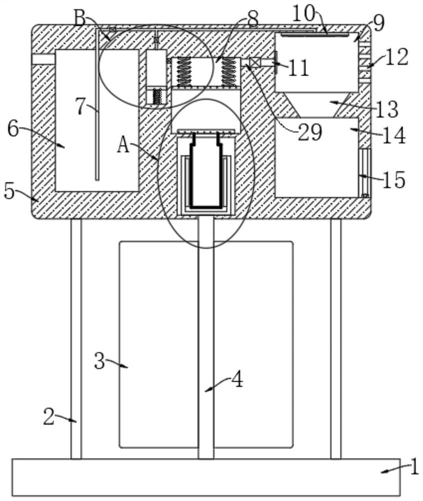
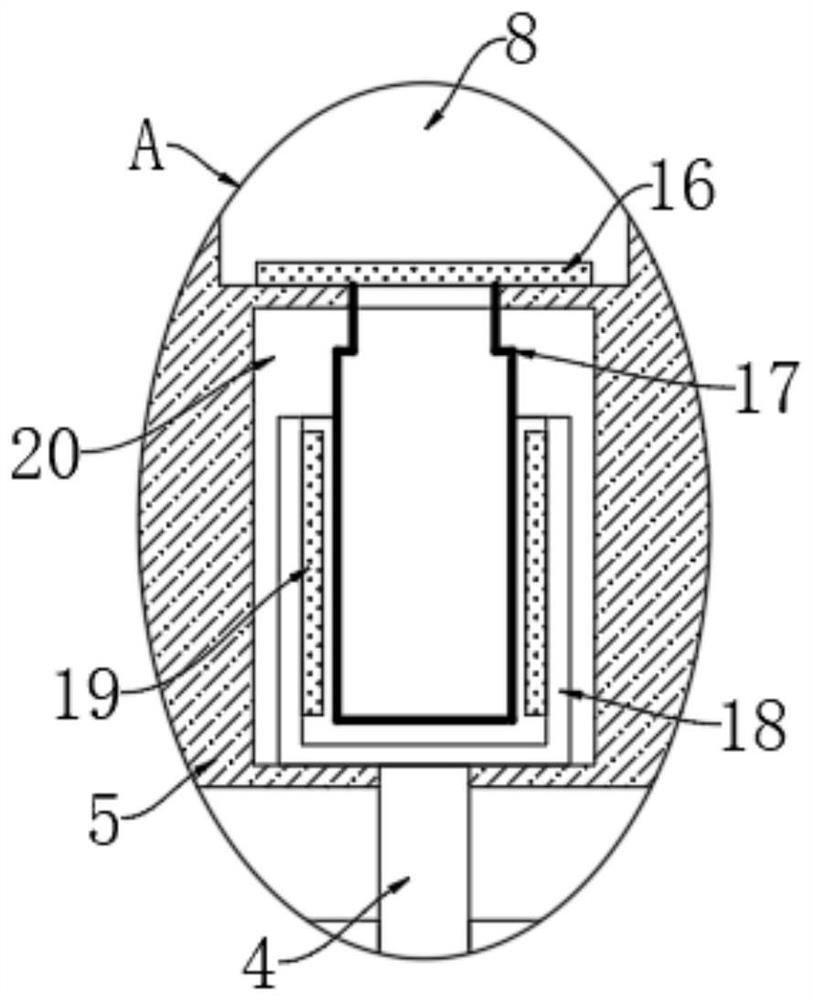
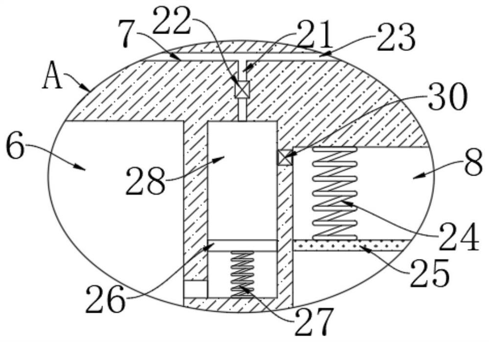
The invention discloses municipal automatic dust removal equipment based on an electromagnetic effect. The municipal automatic dust removal equipment comprises a base and an alternating power generation mechanism, wherein the base is arranged on the two sides of a road, the upper end of the base is fixedly connected with a plurality of connection rods, and the upper ends of the multiple connectionrods are jointly and fixedly connected with a shell; a rotary shaft is arranged between the shell and the base, and the two ends of the rotary shaft are rotationally connected with the upper end of the base and the lower end of the shell correspondingly; the interior of the shell is provided with a water storage chamber, a vertical cavity, a gas cavity and a dust processing chamber from left to right in sequence; the lower portion of the gas cavity is provided with a power generation cavity, and the lower portion of the dust processing chamber is provided with a waste water cavity; and the alternating power generation mechanism comprises a plurality of vertical fan blades arranged in the circumferential direction of the rotary shaft. According to the dust removal equipment, through wind force generated by vehicles coming and going, a dust falling mechanism is driven to operate, dust outside the dust falling mechanism is sucked into the equipment, meanwhile, the interior of the dust falling equipment is washed intermittently, and use is quite convenient.

Description

technical field [0001] The invention relates to the field of environmental protection, in particular to a municipal automatic dust removal device based on electromagnetic effects. Background technique [0002] Environmental protection is the behavior of protecting the natural environment for the well-being of nature and human beings at the level of individuals, organizations or governments. With the vigorous development of industry, environmental protection is also a key issue now. There will be more gatherings on the streets and on the ground. When the vehicle passes by, it will raise the dust and cause discomfort to the passers-by; [0003] Now the solution to this problem is to spray water to reduce dust through precipitation vehicles in some dry weather, but if water spray is used to reduce dust, after the ground evaporates, the dust still exists, that is, the effect of water spray to reduce dust Poor, and a dust removal method with a stronger dust removal effect is wha...

Claims


Application Information

Patent Timeline
Patent Type & Authority Applications(China)
IPC IPC(8): B08B15/04B01D46/10B01D46/00
CPCB08B15/04B01D46/10B01D46/72B01D46/71
Inventor 杨年生
Owner 杨年生
Learn More