Roller way for shear line and shear production line

A cutting line and production line technology, applied in the direction of shearing devices, shearing machine accessories, shearing machine equipment, etc., can solve problems such as uneven wear of the roll surface, affecting production, affecting rolling rhythm, etc., to avoid edge Roller group, improved service life, and wide application prospects

Pending Publication Date: 2020-09-22
CERI TECH +1
View PDF0 Cites 0 Cited by
  • Summary
  • Abstract
  • Description
  • Claims
  • Application Information

AI Technical Summary

Problems solved by technology

However, if the edge device is installed separately, it will affect the rolling rhythm and ultimately affect the output; it will also increase the one-time investment cost, and the cost during operation will also increase
The wider steel plate rolling line is generally wider in width. Usually, the roller table is driven at one end, and the widest roller table is 5000mm wide. One end of the roller table is frequently subjected to torque transmission to the entire roller body, and the entire roller table is transported under stress. Uneven, long-term forward and reverse operation, motor shaft breakage accidents will occur
The width setting of the roller table must be wider than the widest steel plate, but in actual use, products with a medium width are often produced, and the frequency of use of the non-fixed side roller table is low. Long-term operation will cause serious wear on the fixed side roller surface, and the entire roller Uneven surface wear

Method used


Image

  • Roller way for shear line and shear production line
  • Roller way for shear line and shear production line
  • Roller way for shear line and shear production line

Examples


Embodiment Construction

[0024] It should be noted that, in the case of no conflict, the embodiments in the present application and the features in the embodiments can be combined with each other. The present invention will be described in detail below with reference to the accompanying drawings and examples.

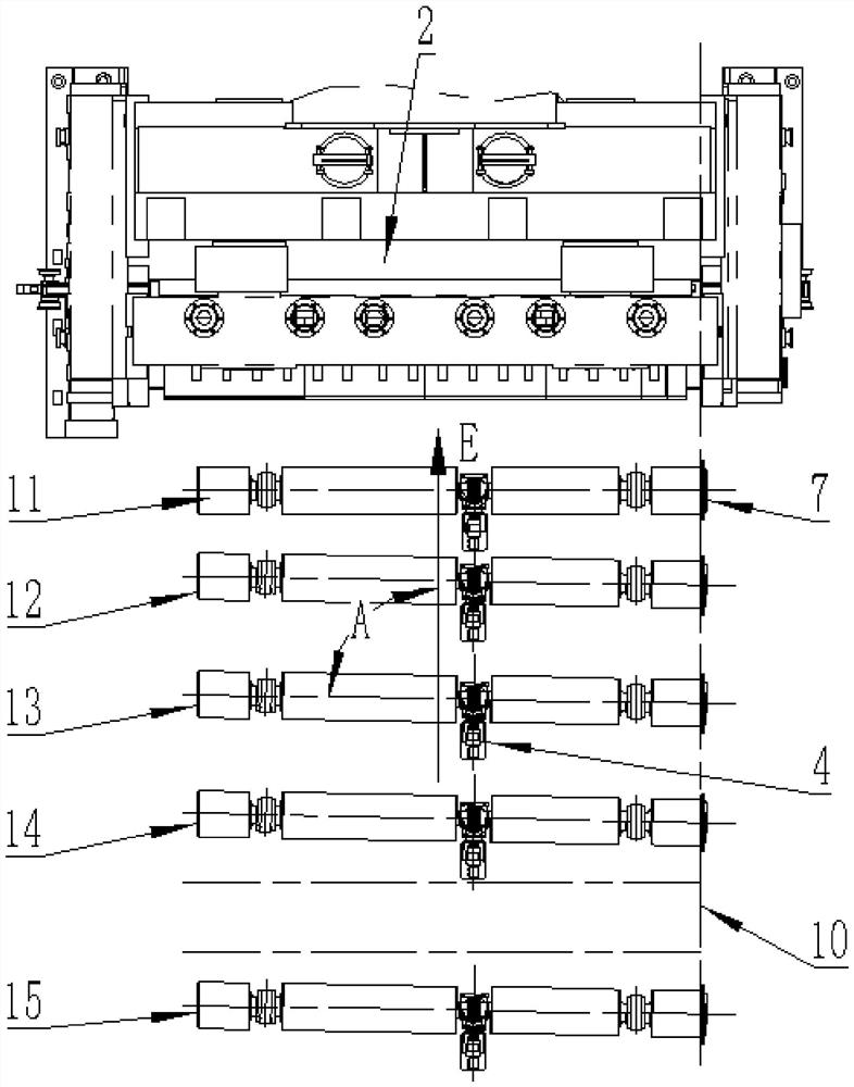
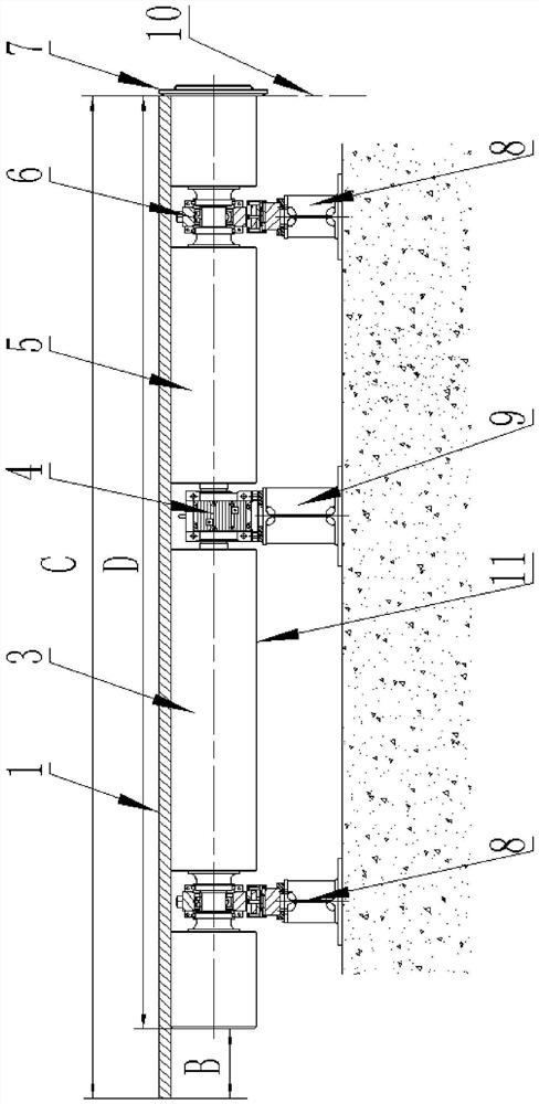
[0025] A roller table for a shear line, comprising a plurality of roller assemblies, along the conveying direction E of the roller table for a shear line, the plurality of roller assemblies are arranged at intervals, and the axis of the plurality of roller assemblies are all located in the same horizontal plane, and the axis of at least one roller assembly in the multiple roller assemblies is set obliquely relative to the transportation direction E, when the steel plate 1 travels along the transportation direction E on the multiple roller assemblies In the process, the assembly of the at least one roller can make the steel plate 1 move to the fixed side 10 of the roller table for the shearing l...


PUM


Abstract

The invention discloses a roller way for a shear line and a shear production line. The roller way for the shear line comprises a plurality of roller assemblies, the plurality of roller assemblies arearranged at intervals in the conveying direction of the roller way for the shear line, the axes of the roller assemblies are all located in the same horizontal plane, the axis of at least one roller assembly in the plurality of roller assemblies is obliquely arranged relative to the conveying direction, in the process that a steel plate (1) advances on the plurality of roller assemblies in the conveying direction, at least one roller assembly can enable the steel plate (1) to move towards a fixed edge (10) of the roller way for the shear line and enable the side edge of the steel plate (1) tobe completely attached to the fixed edge (10). According to the roller way for the shear line and the shear production line, the axes of part of the roller assemblies in the roller way for the shear line are obliquely arranged relative to the conveying direction, in the process that the steel plate advances on the plurality of roller assemblies, automatic side leaning operation can be achieved, anindependent side leaning device does not need to be arranged any more, and cost is saved.

Description

technical field [0001] The invention relates to the field of metallurgical machinery and equipment, in particular to a roller table for a shearing line, or a shearing production line containing the roller table for a shearing line. Background technique [0002] The medium and thick plate shearing line is generally equipped with cutting head shears, double-sided shears and fixed-length shears. These three shears require the steel plate to be close to the fixed side during transportation to ensure the rectangularity and accuracy of the steel plate after shearing. Usually, an edge device is usually installed on the roller table on the entrance side of the shearing machine to ensure that the steel plate can be transported close to the fixed side (ie, the fixed side). However, if the edge device is installed separately, it will affect the rolling rhythm and ultimately affect the output; it will also increase the one-time investment cost, and the cost will also increase during the...

Claims


Application Information

Patent Timeline
Patent Type & Authority Applications(China)
IPC IPC(8): B23D15/08B23D33/00B23Q7/05
CPCB23D15/08B23D33/00B23Q7/05
Inventor 郝建伟王宏亮曹建宁倪延峰
Owner CERI TECH
Why Eureka
Try Eureka