Water drill bit polishing device

A technology for polishing devices and drill bits, which is applied in the direction of grinding drive devices, machine tools for surface polishing, grinding/polishing equipment, etc. It can solve the problems of automatic loading and unloading, low efficiency of manual polishing, etc., and achieves the convenience of taking and replacing Effect

Active Publication Date: 2020-09-22
永州金科地质装备有限公司
View PDF7 Cites 5 Cited by
  • Summary
  • Abstract
  • Description
  • Claims
  • Application Information

AI Technical Summary

Problems solved by technology

[0005] In order to overcome the low efficiency of manual polishing, it is necessary to repeatedly take and replace the drill bit, and the existing new drill bit polishing machine cannot automatically load and unload the shortcomings.

Method used


Image

  • Water drill bit polishing device
  • Water drill bit polishing device
  • Water drill bit polishing device

Examples


Embodiment 1

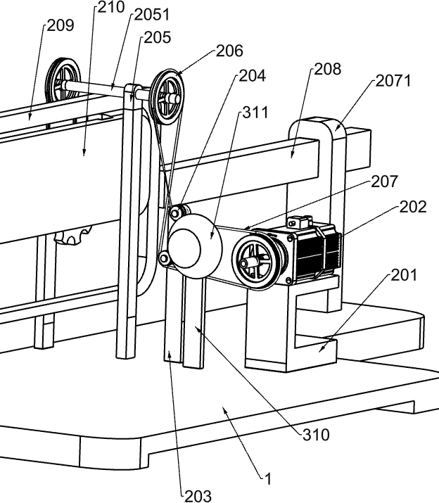
[0041] A water drill bit polishing device, such as figure 1 As shown, it includes a polishing seat 1, a polishing mechanism 2 and a clamping mechanism 3. The polishing mechanism 2 is installed on the right side and the left front side of the polishing seat 1, and a clamping mechanism 3 is provided between the front, rear and rear sides of the polishing seat 1. The mechanism 3 is connected with the polishing mechanism 2 .

[0042] When the water drill bit 6 needs to be polished, the water drill bit 6 is manually held horizontally to make it contact the parts of the clamping mechanism 3, and then the polishing mechanism 2 and the parts in the clamping mechanism 3 are started, and the polishing parts in the polishing mechanism 2 are lowered thereupon. Move the contact water drill bit 6, and then the polishing parts in the polishing mechanism 2 move forward. During the downward movement of the polishing parts in the polishing mechanism 2, the parts in the clamping mechanism 3 move...

Embodiment 2

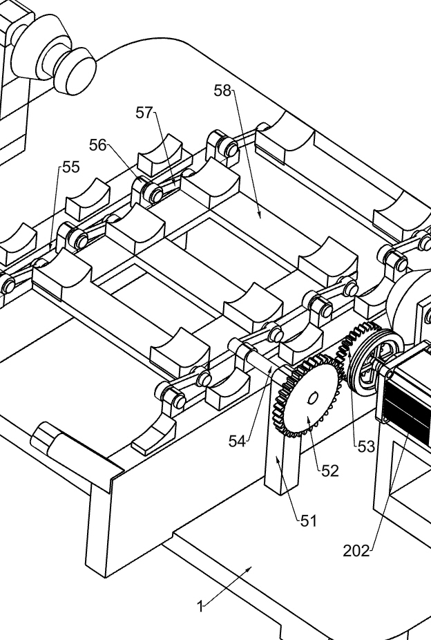
[0044] Specifically, such as Figure 1-4As shown, the polishing mechanism 2 includes a support 201, a reduction motor 202, a first mounting plate 203, a guide wheel 204, a second mounting plate 205, an upper rotating shaft 2051, a first pulley 206, a first flat belt 207, a mounting table 2071, Sliding plate 208, moving frame 209, moving plate 210, polishing head 211, clamping rod 212, arc block 213, third mounting plate 214, card wheel 215, second pulley 216 and second flat belt 217, left front side of polishing seat 1 Bearing 201 is installed, and the top of bearing 201 is provided with decelerating motor 202, and the polishing seat 1 on the right side of bearing 201 is equipped with first mounting plate 203, and the rear side of the first mounting plate 203 top is provided with two guide wheels 204, The right front part of the polishing seat 1 is provided with a second mounting plate 205, the second mounting plate 205 is located on the right side of the first mounting plate ...

Embodiment 3

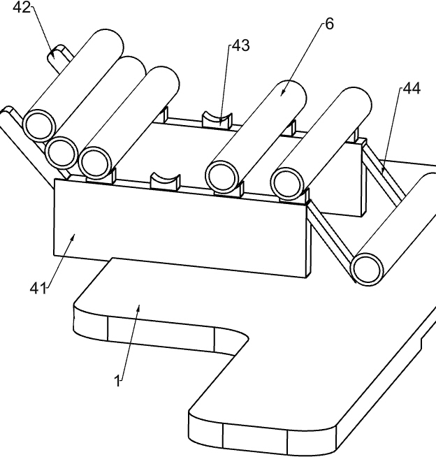
[0049] In particular, refer to figure 1 and Figure 5-6 , also includes a placement mechanism 4, the placement mechanism 4 includes a vertical plate 41, an oblique bar 42, a placement plate 43 and a blanking rod 44, two vertical plates 41 are installed on the right side of the polishing seat 1, and the vertical plate 41 is located at the first block 35 and the second block 311, the upper left side of the vertical plate 41 is provided with a slanting bar 42, the tops of the two vertical plates 41 are uniformly and symmetrically connected with a placement plate 43, and the upper right side of the vertical plate 41 is equipped with a feeding rod 44 .

[0050] The water drill bit 6 is placed on the placement plate 43, and the rightmost water drill bit 6 contacts the second block 311. When the polishing head 211 moves down, the first block 35 moves forward to fix the water drill bit 6, and the polishing head 211 Then the water drill 6 between the first block 35 and the second blo...


PUM


Abstract

The invention relates to a polishing device, in particular to a water drill bit polishing device. According to the water drill bit polishing device, a water drill bit can be automatically fixed, and is polished, and the water drill bit can be automatically replaced. The water drill bit polishing device comprises a polishing base, a polishing mechanism is arranged between the front left side and the right side of the polishing base, a clamping mechanism is arranged between the rear side and the front side of the polishing base, the clamping mechanism is connected with the polishing mechanism, through the polishing mechanism, automatic polishing of the water drill bit can be achieved, after the water drill bit is polished, the polishing head can automatically move upwards to be separated from the water drill bit, through the clamping mechanism, during polishing, the water drill bit is clamped and rotates, after polishing, the clamping mechanism can automatically loosen the water drill bit, through a placing mechanism, manual taking and replacing of the water drill bit can be facilitated, and through an automatic conveying mechanism, automatic replacing of the water drill bit can be achieved.

Description

technical field [0001] The invention relates to a polishing device, in particular to a water drill bit polishing device. Background technique [0002] In order to reduce the surface roughness of the water drill bit, the water drill bit is usually polished. The polishing process requires manual operation. Manually place the water drill bit under the polishing machine to fix it, the motor drives the water drill bit to rotate, and manually move the polishing machine down to touch. The water drill bit, the polishing machine then polishes the water drill bit. After the polishing is completed, the polishing machine is manually lifted up, the water drill bit is taken off, and another water drill bit to be polished is put on. However, this manual grinding of the water drill bit The way of polishing requires too much manual operation, and the water drill bit needs to be replaced manually repeatedly, so the polishing efficiency is low. [0003] Patent CN204843721U discloses a new typ...

Claims


Application Information

Patent Timeline
IPC IPC(8): B24B29/02B24B41/06B24B47/22B24B47/20B24B41/04
CPCB24B29/02B24B41/06B24B47/22B24B47/20B24B41/04
Inventor 龙红辉
Owner 永州金科地质装备有限公司
Why Eureka
Try Eureka