A wood surface gluing mechanism
A wood surface, gluing technology, applied to wood processing appliances, adhesive application devices, manufacturing tools, etc.
- Summary
- Abstract
- Description
- Claims
- Application Information
AI Technical Summary
Problems solved by technology
Method used
Image

Examples
Embodiment 1
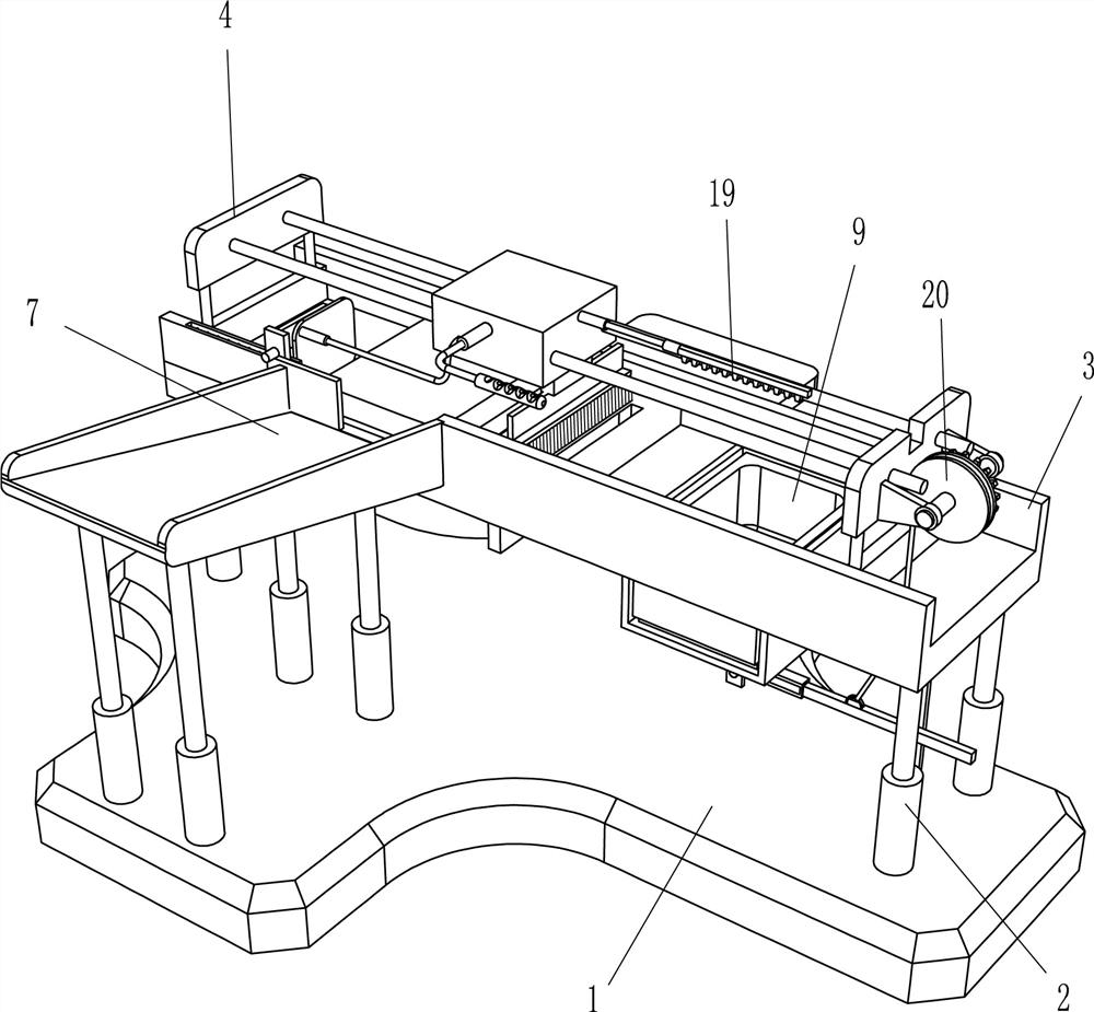
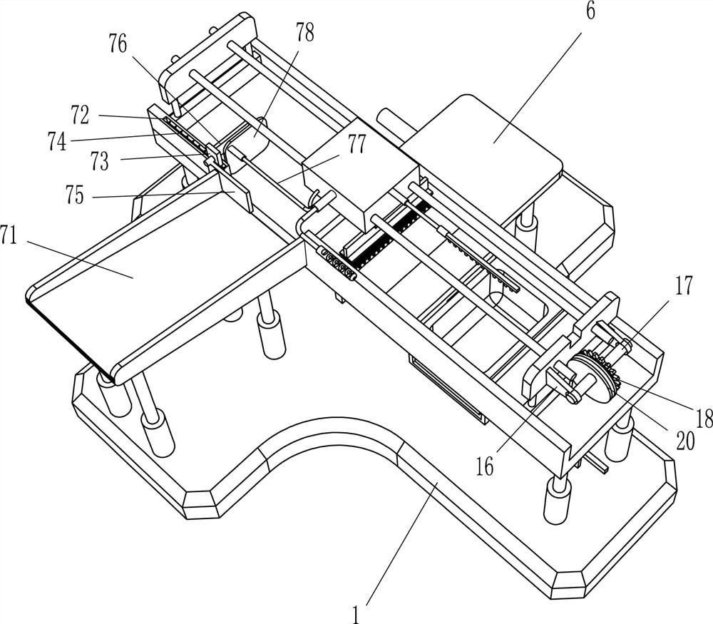
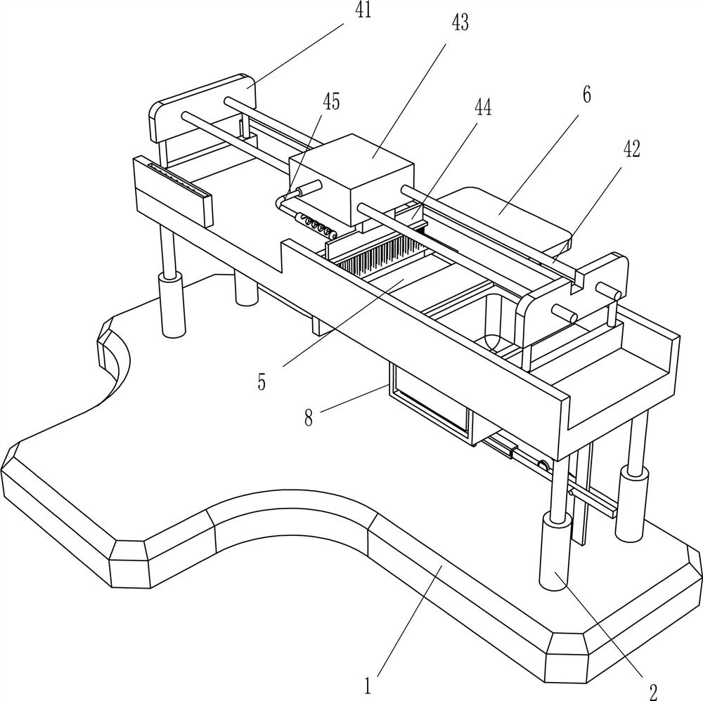
[0035] A wood surface gluing mechanism, such as figure 1 As shown, it includes a base 1, a support column 2, a processing frame 3, a gluing mechanism 4, a placing plate 6, a feeding mechanism 7, a placing frame 8, a glue box 9, a top plate 10, a top rod 11 and a sliding shaft 12, the base 1. Support columns 2 are arranged on the left and right sides in a rectangular shape. A processing frame 3 is installed between the tops of the supporting columns 2. A strip-shaped groove is opened on the rear side of the middle of the processing frame 3. 3. A square groove 5 is opened in the middle, and a placing plate 6 is arranged on the rear side of the middle of the base 1. The placing plate 6 is located on the right rear side of the square groove 5. There is a placing frame 8, a plastic box 9 is slidably arranged inside the placing frame 8, and a top plate 10 is slidably provided inside the placing frame 8. A sliding shaft 12 is arranged between the ends of the rod 11 .
[0036] When ...
Embodiment 2
[0038] refer to Figure 2-3 As shown in the figure, the gluing mechanism 4 includes a mounting plate 41, a guide rod 42, a sliding block 43, a glue brush 44 and a handle 45, and the left and right sides of the processing frame 3 are provided with mounting plates 41. A guide rod 42 is connected between the sides, a sliding block 43 is slidably arranged between the guide rods 42 on both sides, and a glue brush 44 is installed on the right side of the bottom of the sliding block 43. The glue brush 44 is located inside the processing frame 3, before the sliding block 43 A handle 45 is provided on the side.
[0039] Manually place the wood in the parts of the unloading mechanism 7, pour the white latex into the plastic box 9, then hold the handle 45 and move it to the left, the sliding block 43 moves to the left, and the sliding block 43 drives the unloading mechanism 7. The component moves to the left, and the last piece of wood slides into the processing frame 3. Then, manually ...
Embodiment 3
[0043] Specifically, as Figure 4-5 As shown, it also includes a mounting frame 13, a connecting rod 14, a return groove plate 15, a bearing seat 16, a rotating shaft 17, a gear 18, a rack 19, a winding wheel 20, a guide wheel 21 and a pull rope 22. The base 1 is on the right A mounting frame 13 is arranged between the bottom of the processing frame 3 and the lower part of the mounting frame 13. A connecting rod 14 is oscillated on the front side of the lower part of the mounting frame 13. The left end of the connecting rod 14 is installed with a return groove plate 15. The right part of the mounting plate 41 on the right side is provided with bearing seats 16 on the front and rear sides; the bearing seats 16 on both sides are provided with a rotating shaft 17; the rear side of the rotating shaft 17 is equipped with a gear 18; A rack 19 is connected, the rack 19 can be meshed with the gear 18, a winding wheel 20 is arranged in the middle of the rotating shaft 17, a guide wheel...
PUM
 Abstract
Description
Claims
Application Information
 - R&D
- Intellectual Property
- Life Sciences
- Materials
- Tech Scout
- Unparalleled Data Quality
- Higher Quality Content
- 60% Fewer Hallucinations
Browse by: Latest US Patents, China's latest patents, Technical Efficacy Thesaurus, Application Domain, Technology Topic, Popular Technical Reports.
© 2025 PatSnap. All rights reserved.Legal|Privacy policy|Modern Slavery Act Transparency Statement|Sitemap|About US| Contact US: help@patsnap.com