Touch display apparatus having cover lens structure

a technology of touch display and lens structure, which is applied in the direction of electrical apparatus casings/cabinets/drawers, instruments, computing, etc., can solve the problems of increasing manufacturing cost, increasing manufacturing cost, and glass material weight being greater than that of plastic material, so as to save the manufacturing cost of touch display apparatus, improve manufacturing efficiency, and improve glue

Inactive Publication Date: 2012-09-06
HANNSTAR DISPLAY CORPORATION
View PDF9 Cites 12 Cited by
  • Summary
  • Abstract
  • Description
  • Claims
  • Application Information

AI Technical Summary

Benefits of technology

[0004]One objective of the present invention is to provide a touch display apparatus having a cover lens structure. The touch display apparatus includes one or more segment height for embedding and locating component layers such as touch sensing layer and display panel therein. The above manner can improve the glue applied to the conventional component layers to save the manufacturing cost of the touch display apparatus, solve the problems of reworking process, and increase the manufacturing efficiency.
[0005]Another objective of the present invention is to provide a touch display apparatus having a cover lens structure. The touch display apparatus includes one or more segment height for embedding and locating component layers such as touch sensing layer and display panel therein. The above manner can improve the machining characteristic of the cover lens structure and effectively reduce the weight of touch display apparatus for portability.
[0006]According to the above objectives, the present invention sets forth a touch display apparatus having a cover lens structure. The cover lens structure protects the touch display apparatus from damage wherein the touch display apparatus further includes a touch sensing layer, a display panel and a backlight module. The cover lens structure further includes a substrate, a first segment height and a side-wall portion. The first segment height protrudes from the substrate wherein the first segment height and the substrate forms a first receiving space to allow the first segment height to retain the touch sensing layer. The side-wall portion extends and bends from a side edge of the substrate wherein the side-wall portion has a locking portion for buckling the backlight module. The cover lens structure further includes a second segment height protruding from the first segment height wherein the second segment height and the first segment height form a second receiving space to allow the second segment height to retain the display panel.
[0008]In the present invention, the touch display apparatus includes one or more segment height for embedding and locating component layers therein. It improves the glue for assembling the conventional component layers to save the manufacturing cost of the touch display apparatus, solve the problems of reworking process, and increase the manufacturing efficiency.

Problems solved by technology

However, disadvantageously, the glass material is hard to machine or polish and thus increases manufacturing cost.
Further, the weight of the glass material is greater than that of the plastic material to decrease the portability of electronic device.
Such the situation makes the circuit elements on the touch sensing layer and display panel fall off if the circuit elements are attached to the glue.
That is, the touch sensing layer and display panel are damaged so that the touch screen are reworked and the manufacturing efficiency is reduced.

Method used


Image

  • Touch display apparatus having cover lens structure
  • Touch display apparatus having cover lens structure
  • Touch display apparatus having cover lens structure

Examples


first embodiment

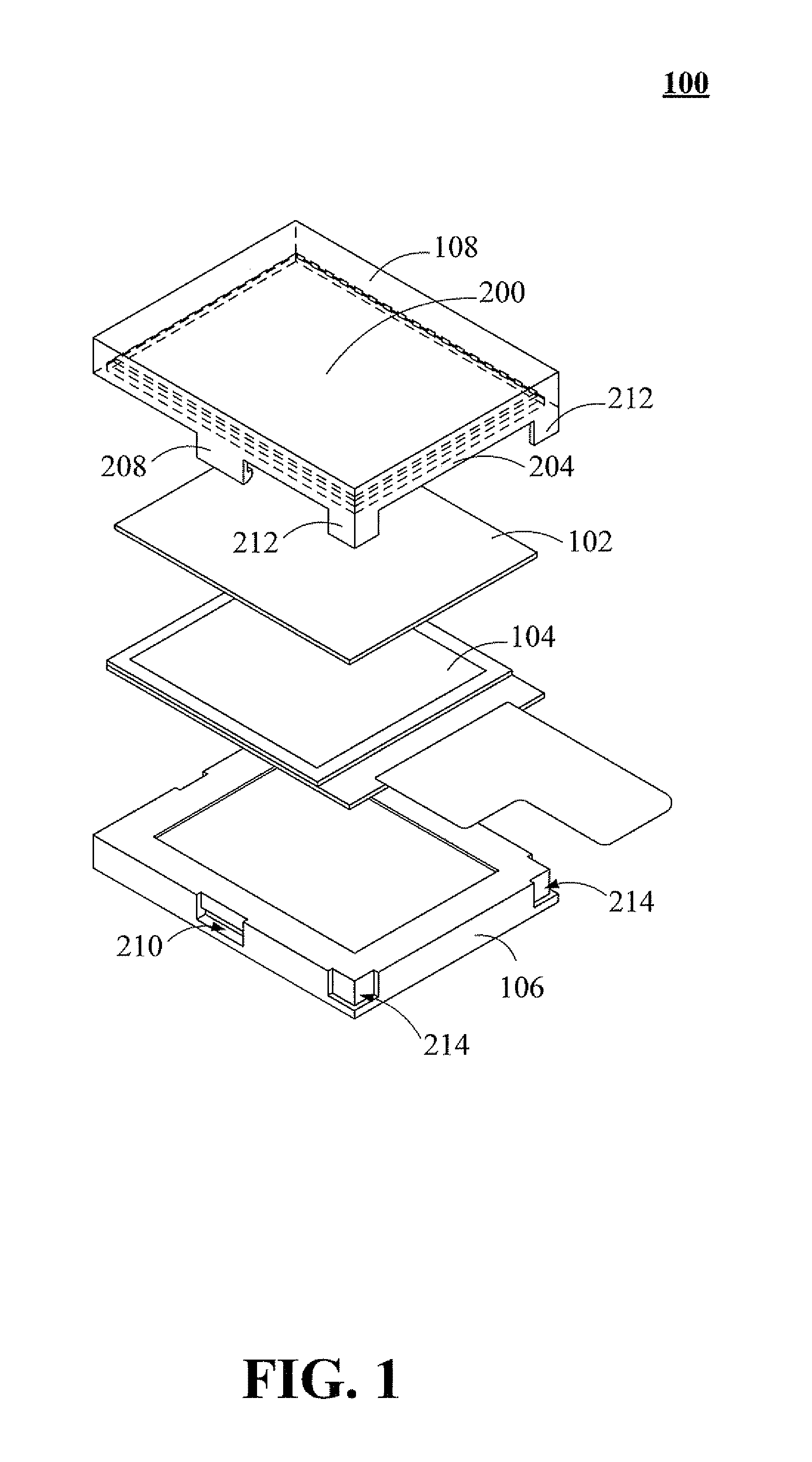
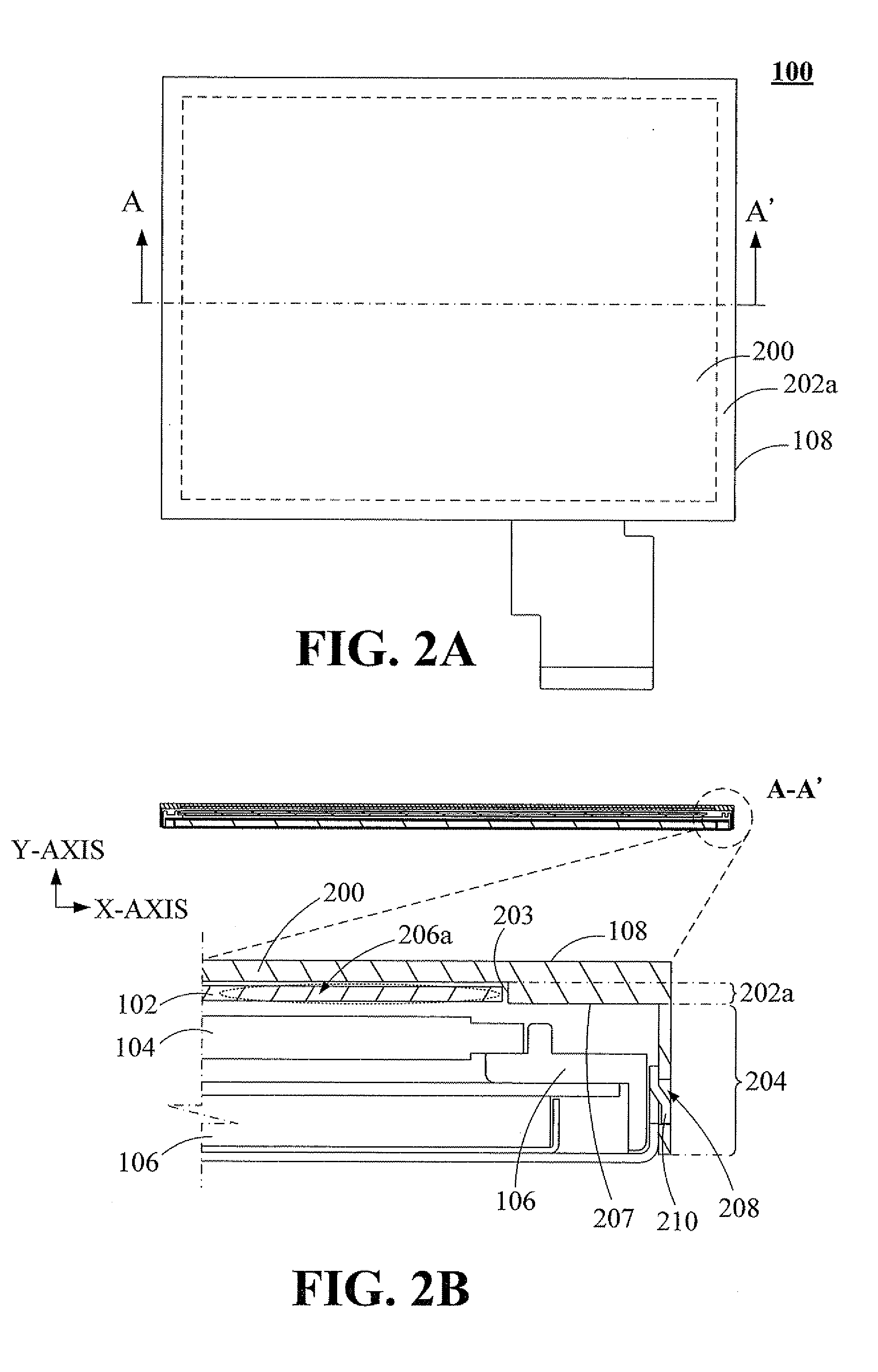
[0018]Please refer to FIG. 2A and FIG. 2B. FIG. 2A is a schematic top view of the touch display apparatus 100 according to the present invention. FIG. 2B is a schematic cross-sectional view and a local enlarged view of the touch display apparatus 100 having a cover lens structure 108 in FIG. 2A along the line A-A′ according to one embodiment of the present invention. The cover lens structure 108 further includes a substrate 200, a first segment height 202a and a side-wall portion 204. The first segment height 202a protrudes from the substrate 200 wherein the first segment height 202a and the substrate 200 forms a first receiving space 206a so that the first segment height 202a retains the touch sensing layer 102. That is, a lateral surface 203 of the first segment height 202a and a partial surface of the substrate 200 construct the first receiving space 206a for retaining the touch sensing layer 102. Specifically, the lateral surface 203 of the first segment height 202a contacts and...

second embodiment

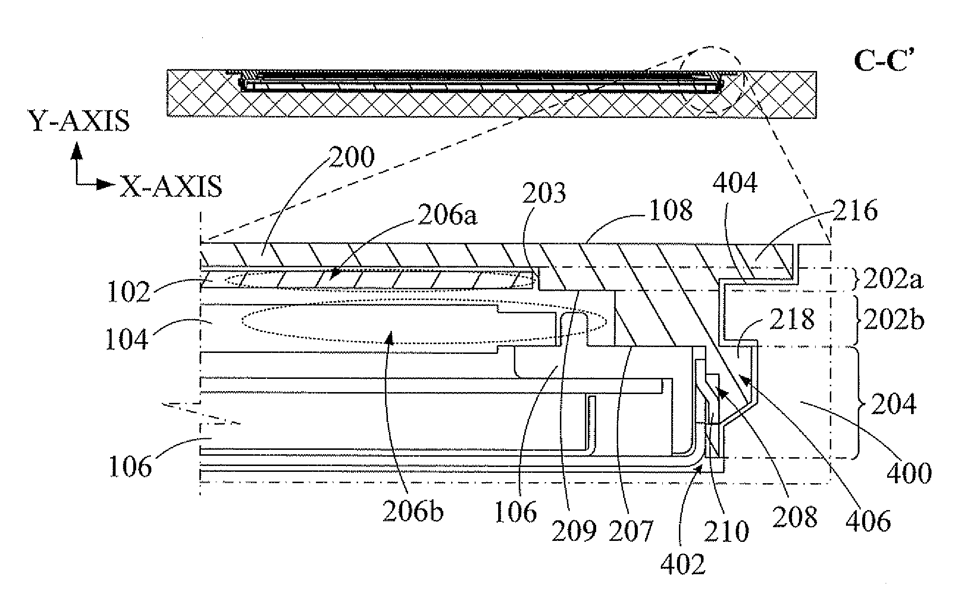
[0021]Please refer to FIG. 3A and FIG. 3B. FIG. 3A is a schematic top view of the touch display apparatus 100 according to the present invention. FIG. 3B is a schematic cross-sectional view and a local enlarged view of the touch display apparatus 100 having a cover lens structure 108 in FIG. 3A along the line B-B′ according to one embodiment of the present invention. The cover lens structure 108 in FIG. 3A and FIG. 3B is similar to the cover lens structure 108 in FIG. 2A and FIG. 2B. The difference is that the cover lens structure 108 in FIG. 2A and FIG. 2B further includes a second segment height 202b protruding from the first segment height 202a wherein the second segment height 202b and the first segment height 202a form a second receiving space 206b so that the second segment height 202b retains the display panel 104. That is, a lateral surface 203 of the second segment height 202b and the side-wall portion 204 construct the second receiving space 206b for retaining the display ...


PUM


Abstract

A touch display apparatus having a cover lens structure is described. The touch display apparatus includes a touch sensing layer, a display panel adjacent to the touch sensing layer, a backlight module adjacent o the display panel and a cover lens structure. The cover lens structure includes a substrate, a first segment height and a side-wall portion. The first segment height protrudes from the substrate wherein the first segment height and the substrate forms a first receiving space to allow the first segment height to retain the touch sensing layer. The side-wall portion extends and bends from a side edge of the substrate wherein the side-wall portion has a locking portion for buckling the backlight module.

Description

FIELD OF THE INVENTION[0001]The present invention relates to a display apparatus having a cover, and more particularly relates to a touch display apparatus having a cover lens structure.BACKGROUND OF THE INVENTION[0002]Currently, with the rapid development of the information technology, touch technique is widely applicable to a variety of electronic devices having display panels for inputting the message to these electronic devices. The user can easily read and browse the information on the display units or transmits the inputted messages by the electronic devices if the user touches the display panels with the finger or stylus pen. Such the inputting manner of the message or information replaces the keypad or keyboard used in the conventional electronic device. For example, since iPhone, a registered trademark of Apple Corporation, is increasingly popular in today's mobile phone market, touch screen attracts a great of attention of the manufacturers. In order to increase the contac...

Claims


Application Information

Patent Timeline
Patent Type & Authority Applications(United States)
IPC IPC(8): G06F3/041H05K7/00
CPCG06F2203/04103G06F3/041G02F2201/465G02F2001/133331G02F1/133308G06F3/0412G02F1/133331
Inventor TSENG, CHIEN-HSIANGCHANG, KE-CHINTENG, CHIA-FENG
Owner HANNSTAR DISPLAY CORPORATION
Why Eureka
Try Eureka