Injection mold

A technology for injection molds and mold bases, which is used in cleaning methods and utensils, removal of smoke and dust, chemical instruments and methods, etc., can solve the problems of solidification of raw materials at the bottom of the mold cavity, easy generation of air bubbles in parts, and reduction of the qualified rate of parts. The effect of uniformity, improved cleanliness, and increased production costs

Inactive Publication Date: 2020-09-22
邓玉欣
View PDF16 Cites 5 Cited by
  • Summary
  • Abstract
  • Description
  • Claims
  • Application Information

AI Technical Summary

Problems solved by technology

[0003] At present, the raw material of the injection mold is injected by a discharge port, and the injection molding time is long, which causes the raw material at the bottom of the mold cavity to solidify prematurely, and the formed parts are prone to air bubbles, which reduces the qualified rate of the parts. Therefore, the invention provides an injection molding Molds to meet people's needs

Method used


Image

  • Injection mold
  • Injection mold
  • Injection mold

Examples


Embodiment Construction

[0037] The preferred embodiments of the present invention will be described below in conjunction with the accompanying drawings. It should be understood that the preferred embodiments described here are only used to illustrate and explain the present invention, and are not intended to limit the present invention.

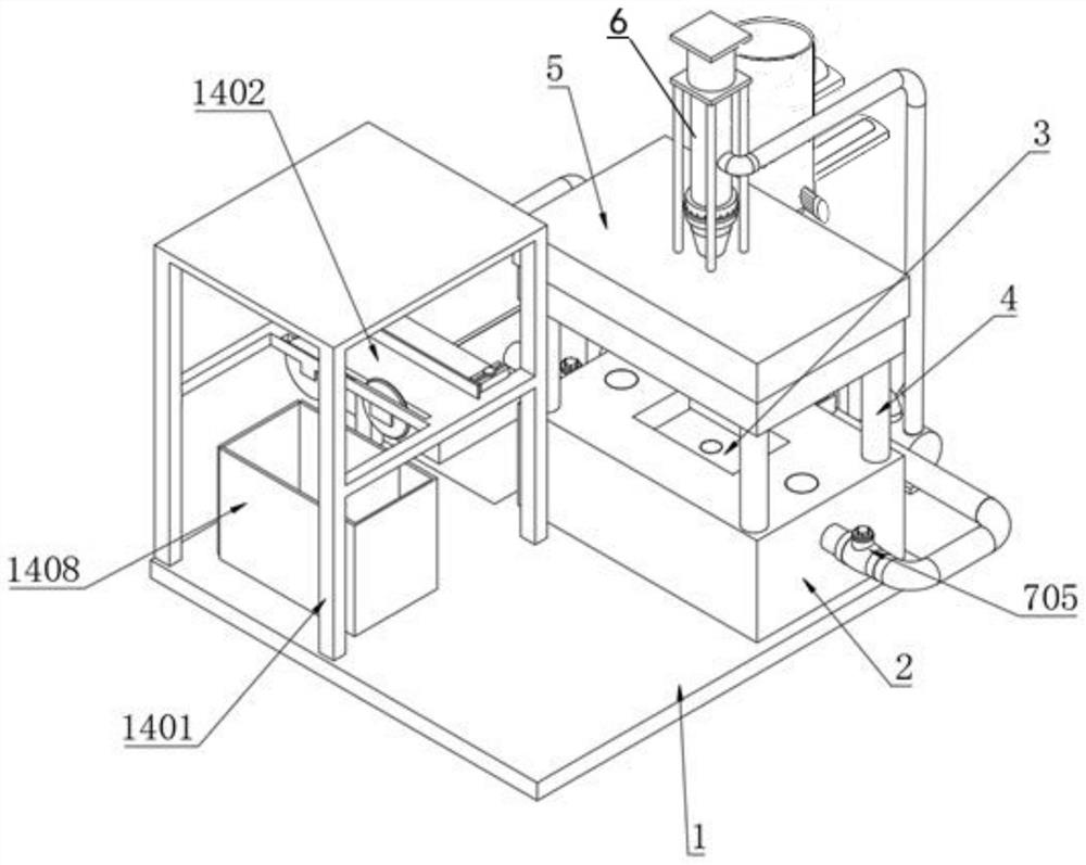
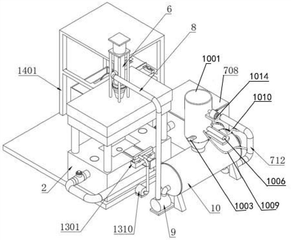
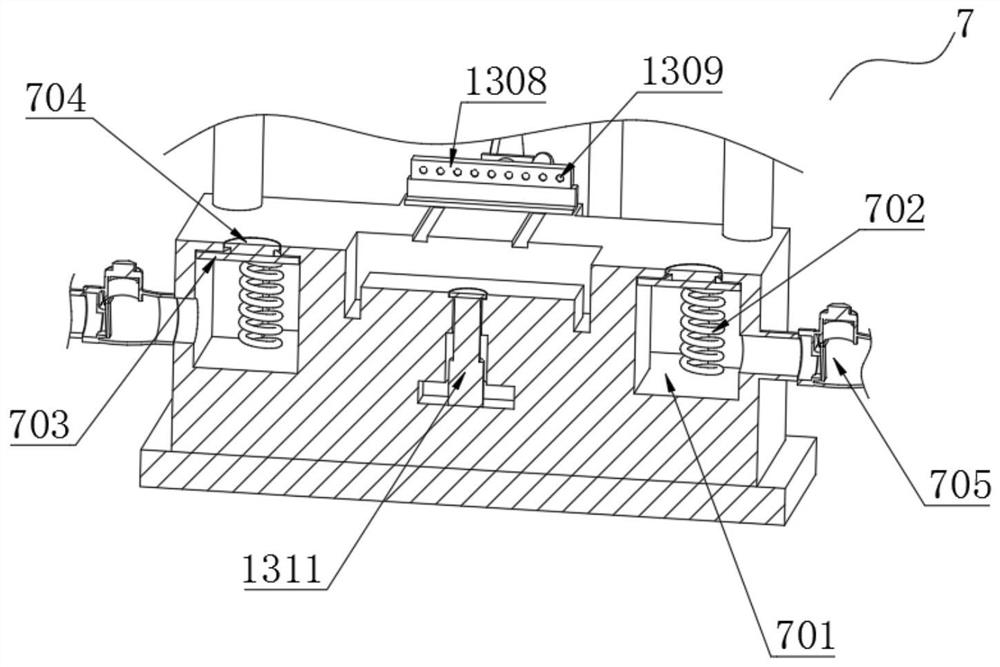
[0038] Example: such as Figure 1-14An injection mold shown includes a base 1, a heat exchange mechanism 7, a raw material tank 10, an adjustment mechanism 11, a discharge mechanism 12, the retrieving mechanism 13 and a trimming mechanism 14, and the feeding hopper 1001 of the raw material tank 10 is built in There is a circular flap 1002, the circular flap 1002 is fixedly connected to the output shaft of the flap motor 1003, the side wall of the feeding hopper 1001 is fixedly connected with a first fixed frame 1004, and the first fixed frame 1004 is fixed with a plurality of legs 1005 with electric telescopic Rod 1006, the rod body of the electric telescopic rod 10...


PUM


Abstract

The invention discloses an injection mold. The injection mold is characterized in that a feeding hopper of a raw material tank is internally provided with a round turning plate, the round turning plate is fixedly connected with an output shaft of a turning plate motor, a first fixing frame is fixedly connected to the side wall of the feeding hopper, an electric telescopic rod is fixed to the firstfixing frame through a plurality of supporting feet, a rod body of the electric telescopic rod is fixedly connected with a push block, the push block is provided with a hollow cavity, one side of thehollow cavity is in communication with a drainage pipe through a water inlet hose with length allowance, the other side of the hollow cavity is in communication with the drainage pipe through a wateroutlet hose with length allowance, and the communication point of the water inlet hose and the drainage pipe is located in front of the communication point of the water outlet hose and the drainage pipe; the water inlet hose is provided with a first one-way valve pointing to the hollow cavity, the water outlet hose is provided with a second one-way valve pointing to the drainage pipe, a second fixing frame is further fixedly connected to the side wall of the feeding hopper, an exhaust fan is fixedly connected to the second fixing frame, an inlet pipe of the exhaust fan communicates with the upper end of the feeding hopper, a limiting bolt is screwed into the feeding hopper on the opposite side of the push block, and when the round turning plate is located at the horizontal position, the right side of the round turning plate makes contact with the bottom end of the push block and the left side of the round turning plate makes contact with the bottom end of the limiting bolt.

Description

technical field [0001] The invention relates to the technical field of injection molds, in particular to an injection mold. Background technique [0002] Injection molding is a tool for producing plastic products, and it is also a tool for giving plastic products a complete structure and precise dimensions. Injection molding is a processing method used in the mass production of certain complex-shaped parts. Specifically, it refers to melting plastic by heat. The injection molding machine is injected into the mold cavity under high pressure, and after cooling and solidification, the molded product is obtained. The injection mold is divided into thermosetting plastic mold, automobile mold and thermoplastic plastic mold according to the molding characteristics. According to the molding process, it is divided into transfer mold, blow mold, casting mold Plastic molds, thermoforming molds, hot compression molds and injection molds, etc. The hot compression molds can be divided int...

Claims


Application Information

Patent Timeline
Patent Type & Authority Applications(China)
IPC IPC(8): B29C45/00B29C45/18B29C45/26B29C45/40B29C45/46B08B15/04B29C45/53B29C45/58B29C45/67B29C45/72B29C45/73B29C45/74B29C37/02
CPCB08B15/04B29C45/0055B29C45/0084B29C45/18B29C45/26B29C45/4005B29C45/46B29C45/53B29C45/58B29C45/67B29C45/7207B29C45/73B29C45/74B29C2045/0058B29C2045/0077
Inventor 邓玉欣
Owner 邓玉欣
Why Eureka
Try Eureka