Biped robot lower limb structure based on modular joints

A biped robot and modular joint technology, applied in the field of lower limb structure of biped robots, can solve the problems of large inertia, unfavorable stable walking of biped robots, low center of gravity, etc., and achieve easy maintenance, improve interchangeability, and reduce costs. Effect

Active Publication Date: 2020-09-22
敬科(深圳)机器人科技有限公司
8 Cites 2 Cited by

AI-Extracted Technical Summary

Problems solved by technology

[0004] The above-mentioned existing technical solutions have the following defects: the ankle motor is arranged at the ankle, and the knee joint motor is arranged at the knee joint, so that th...

Method used

Referring to Fig. 1 and Fig. 2, it is a kind of biped robot lower limb structure based on modular joint disclosed by the present invention, which has raised the center of gravity of the biped, so that the inertia of the biped can be smaller when swinging, which helps For stable walking with two feet, it includes left and right feet, which are vertically arranged in parallel, and the parts on the left and right feet are mirror images of each other, so as to realize the interchangeability of the parts on the left and right feet; the single foot includes : hip joint mechanism 1, thigh member 2, knee joint mechanism 3 and calf mechanism 4, the lower end of hip joint mechanism 1 is rotationally connected with the upper end of thigh member 2, and hip joint mechanism 1 is used to drive knee joint mechanism 3 and calf mechanism 4 to swing back and forth; The knee joint mechanism 3 is fixedly arranged on the thigh member 2, and the knee joint mechanism 3 is used to drive the calf mechanism 4 to swing back and forth; the upper end of the calf mechanism 4 is rotationally connected with the lower end of the thigh member 2 and is driven by the knee joint mechanism 3 to rotate back and forth; At this time, the knee joint mechanism 3 on one foot first drives the calf mechanism 4 to rotate backward, s...

Abstract

The invention relates to a biped robot lower limb structure based on modular joints. The biped robot lower limb structure comprises hip joint mechanisms, thigh pieces, knee joint mechanisms and shankmechanisms, the lower ends of the hip joint mechanisms are rotationally connected with the thigh pieces, and the hip joint mechanisms are used for driving the knee joint mechanisms and the shank mechanisms to swing front and back, swing left and right and rotate inside and outside; the knee joint mechanisms are fixedly arranged on the thigh pieces and used for driving the shank mechanisms to swingfront and back; and the shank mechanisms are movably arranged at the lower ends of the thigh pieces and driven by the knee joint mechanisms to rotate forwards and backwards. The gravity center of thelegs of the biped robot can be adjusted upwards, so that the inertia of the legs of the biped robot is smaller during swinging, and the biped robot can walk more stably and quickly.

Application Domain

Technology Topic

Image

  • Biped robot lower limb structure based on modular joints
  • Biped robot lower limb structure based on modular joints
  • Biped robot lower limb structure based on modular joints

Examples

  • Experimental program(1)

Example Embodiment

[0036] The present invention will be further described in detail below with reference to the accompanying drawings.
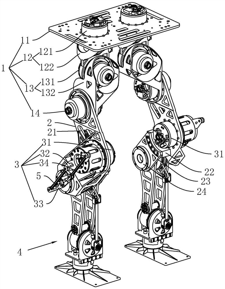
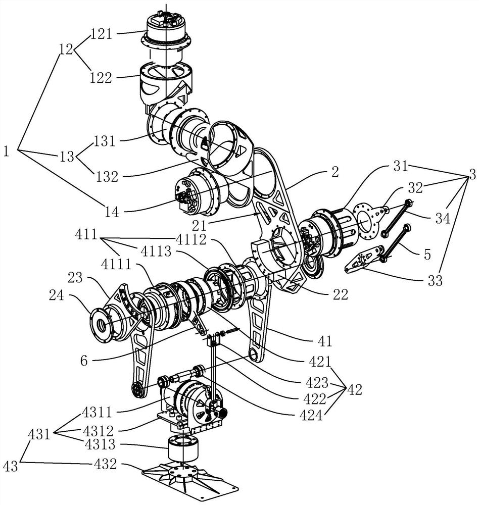
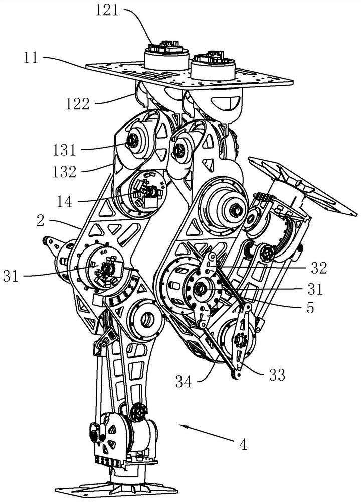
[0037] refer to figure 1 and figure 2 , which is a lower limb structure of a biped robot based on modular joints disclosed in the present invention, which raises the center of gravity of the feet, so that the inertia of the feet will be smaller when swinging, which is helpful for the stable walking of the feet, including: Left and right feet, the left and right feet are vertically parallel, and the parts on the left and right feet are mirror images of each other, so as to facilitate the exchange of the upper parts of the left and right feet; the single foot includes: hip joint mechanism 1, thigh piece 2 , Knee joint mechanism 3 and calf mechanism 4, the lower end of the hip joint mechanism 1 is rotatably connected with the upper end of the thigh piece 2, the hip joint mechanism 1 is used to drive the knee joint mechanism 3 and the calf mechanism 4 to swing back and forth; the knee joint mechanism 3 is fixedly arranged on the thigh piece 2, the knee joint mechanism 3 is used to drive the calf mechanism 4 to swing back and forth; the upper end of the calf mechanism 4 is rotatably connected with the lower end of the thigh piece 2 and is driven to rotate back and forth by the knee joint mechanism 3; when walking on both feet, the knee joint mechanism 3 on one foot First, the calf mechanism 4 is driven to rotate backward, so that the calf mechanism 4 is lifted backward, and then the hip joint mechanism 1 drives the thigh piece 2 to rotate forward, so that the thigh piece 2, the knee joint mechanism 3 and the calf mechanism 4 rotate forward together for a certain amount of time. At this time, the knee joint mechanism 3 lowers the calf mechanism 4 down and returns to the original state, so as to achieve the purpose of taking one step forward with one foot. The connection moves up a certain distance, so that the center of gravity of one foot moves up, and when the foot swings, the inertia generated by the foot will be smaller, and the walking will be more stable.
[0038] refer to figure 1 and figure 2 , the hip joint mechanism 1 includes: a hip joint connector 11, an internal and external rotation component 12, a left and right rotation component 13, and a front and rear rotation component 14. Both feet share a hip joint connector 11, and the hip joint connector 11 is flat and made of aluminum alloy. Material, the hip joint connector 11 is arranged horizontally, and the hip joint connector 11 connects the internal and external rotation components 12 on the adjacent two legs together; the internal and external rotation components 12 are fixedly arranged on the hip joint connector 11 and are used to drive the left and right rotation components 13 rotates inside and outside; the left and right rotating components 13 are fixedly arranged at the lower end of the inside and outside rotating components 12 and are used to drive the front and rear rotating components 14 to rotate left and right; .
[0039] refer to figure 1 and figure 2 Specifically, the internal and external rotation assembly 12 includes a first hip joint driving member 121 and a first hip joint connecting member 122, the first hip joint driving member 121 is a servo motor, and an aluminum alloy is welded on the outer surface of the first hip joint driving member 121. A flange made of alloy material, the flange is defined as the first fixed flange, one end of the output shaft of the first hip joint driving member 121 vertically passes through the hip joint connecting member 11, and the hip joint connecting member 11 is provided with a perforation For the first driving member 121 of the hip joint to pass through, the first fixing flange on its outer surface is in contact with the upper surface of the hip joint connecting member 11, and then the first fixing flange is connected to the hip joint connecting member 11 by screws. are fixedly connected, so that the first driving member 121 of the hip joint is fixed on the connecting member 11 of the hip joint; an aluminum alloy flange is coaxially welded on the output shaft of the first driving member 121 of the hip joint. Defined as the first output flange, the first output flange is fixedly connected with the upper end of the first connecting piece 122 of the hip joint through screws, and the lower end of the first connecting piece 122 of the hip joint is fixedly connected with the upper end of the left and right rotating components 13; After the first driving member 121 is energized, the output shaft of the first driving member 121 of the hip joint is output to rotate, and the first output flange can drive the first connecting member 122 of the hip joint to rotate around the axis of the output shaft, thereby making the joint with the hip joint rotate. The left-right rotation assembly 13 fixedly connected with the first connecting member 122 rotates on a horizontal plane, so that the biped robot can turn.
[0040] refer to figure 1 and figure 2 , the left and right rotation assembly 13 includes a second hip joint driving member 131 and a second hip joint connecting member 132, the second hip joint driving member 131 is also a servo motor, and an aluminum alloy is also welded on the outer surface of the second hip joint driving member 131. A flange made of alloy, the flange is defined as a second fixed flange, and one end of the output shaft of the second hip joint driving member 131 passes horizontally forward from the rear surface of the lower end of the first hip joint connecting member 122 The first connecting piece 122 of the hip joint, and the second fixing flange is in contact with the rear surface of the lower end of the first connecting piece 122 of the hip joint. At this time, the second fixing flange and the first connecting piece of the hip joint are made by screws. 122 is fixedly connected, so that the second hip joint driving member 131 is fixed on the first hip joint connecting member 122, and the first hip joint connecting member 122 is provided with a perforation for the hip joint second driving member 131 to pass through; The output shaft of the driving member 131 is also coaxially welded with a flange made of aluminum alloy, which is defined as the second output flange, and the output shaft of the second driving member 131 of the hip joint passes through the second output flange of the hip joint. The upper end of the upper end of the connecting piece 132, and the second output flange is in contact with the upper end of the second hip joint connecting piece 132 and is fixedly connected by screws, and the upper end of the second hip joint connecting piece 132 is provided with a second driving piece 131 for the hip joint. Through the hole through which the output shaft passes, the lower end of the second hip joint connecting member 132 is fixedly connected to the front and rear rotating assembly 14; at this time, after the second hip joint driving member 131 is powered on, the output shaft of the second hip joint driving member 131 will pass through the second hip joint driving member 131. The two output flanges drive the second connecting piece 132 of the hip joint to rotate left and right on the vertical plane, so that the front and rear rotating components 14 are also rotated left and right, so that the feet can be opened to avoid obstacles.
[0041] refer to figure 1 and figure 2 , the front and rear rotation assembly 14 includes a third drive part of the hip joint, the third drive part of the hip joint is also a servo motor, and an aluminum alloy flange is also welded on the outer surface of the third drive part of the hip joint. The flange plate Defined as the third fixed flange, one end of the output shaft of the third hip joint driving member horizontally passes through the lower end of the second hip joint connecting member 132, and the third fixed flange is in contact with one side surface of the second hip joint connecting member 132. Connected and fixedly connected by screws, the second hip joint connecting piece 132 is provided with perforations for the third hip joint driving piece to pass through; an aluminum alloy flange is coaxially fixed on the output shaft of the hip joint third driving piece The flange is defined as the third output flange, the upper end of the thigh member 2 is provided with a perforation for the output shaft of the third driving member of the hip joint to pass through, and the output shaft of the third driving member of the hip joint passes through When the upper end of the thigh piece 2 is perforated, the third output flange is in contact with one side surface of the upper end of the thigh piece 2 and is fixedly connected by bolts; when the third driving piece of the hip joint is energized, the output shaft of the third driving piece of the hip joint outputs Rotate, so that the third flange drives the thigh piece 2 to rotate back and forth, so that the thigh piece 2 takes a step forward, thereby realizing the purpose of walking.
[0042] refer to figure 1 and figure 2 , the thigh piece 2 is a V-shaped stainless steel sheet body, and the middle of the thigh piece 2 protrudes forward, so that a part of the back side of the thigh piece 2 is freed, so that the knee joint mechanism 3 can drive the calf mechanism 4 backward to have a greater rotation. A plurality of hollow holes 21 are evenly opened on the thigh piece 2, so that the quality of the thigh piece 2 is greatly reduced, thereby greatly reducing the quality of the feet, so that the feet can walk more flexibly.
[0043] refer to figure 1 and figure 2 The knee joint mechanism 3 includes: a knee joint driving member 31, a first linkage member 32, a second linkage member 33 and a first connecting rod 34, the knee joint driving member 31 is also a servo motor, and the outer surface of the knee joint driving member 31 is A flange made of aluminum alloy is also welded, which is defined as the fourth fixed flange. The flange is in contact with one side surface of the bent part of the thigh piece 2, and then the fourth flange is fixedly connected with the thigh piece 2 through screws, so that the knee joint driver 31 is fixed on the thigh piece 2; the knee joint driver 31 A flange made of aluminum alloy is coaxially welded on the output shaft of the 2000A, the flange is defined as the fourth output flange, and the middle of the first linkage 32 is fixed on the fourth output flange by screws. The first linkage member 32 is in the shape of a prismatic sheet and is made of aluminum alloy. One end of the first linkage member 32 is connected with one end of the first connecting rod 34 through a rivet. The second linkage member 33 is also in the shape of a prismatic sheet and is made of aluminum alloy. , the second linkage member 33 is fixedly arranged on the upper end of the calf mechanism 4, one end of the second linkage rod is connected with the other end of the first link rod 34 through rivets, and the position where the second linkage member 33 is connected with the first link rod 34, the first link A link 32 is connected to the first link 34 on the same side, the second link 33 rotates on the same plane as the first link 32 , and the first link 32 is on the front side of the second link 33 .
[0044] refer to figure 1 and image 3 , when the knee joint driver 31 is energized and the output shaft rotates clockwise, the first linkage member 32 rotates clockwise around the axis of the output shaft of the knee joint driver 31 , so that the first linkage member 32 is connected with the first link 34 The end of the first link 34 pushes the first link 34 to move backward, and after the first link 34 moves backward, the end of the first link 34 connected with the second link 33 will be driven, so that the second link 33 Drive the calf mechanism 4 to rotate backward together, so that the calf mechanism 4 rotates to the inner side of the bend of the thigh piece 2. At this time, the third driving part of the hip joint drives the thigh piece 2 to rotate forward by a certain angle, so that the knee joint mechanism 3 , the thigh member 2 and the calf mechanism 4 also move forward, and then the output shaft of the knee joint driving member 31 rotates counterclockwise, so that the calf mechanism 4 is lowered down and returns to the original state, and the calf mechanism 4 also reaches forward. purpose of a step.
[0045] refer to figure 1 and figure 2 , in order to reduce the burden of the first link 34, a second link 5 is also provided between the first link 32 and the second link 33, the second link 5 is parallel to the first link 34 and is in the first link Above the connecting rod 34, the two ends of the second connecting rod 5 are also connected with the first linking member 32 and the end of the second linking member 33 away from the first connecting rod 34 through rivets. 34. The second linkage 33 and the second link 5 form a four-link mechanism. Compared with the transmission of the synchronous pulley, the setting of the four-link mechanism is less likely to cause delay in the transmission of force, and the mechanism is controlled. The response speed will be faster and the mechanism will be more stable.
[0046] refer to figure 1 and figure 2The calf mechanism 4 includes: a calf piece 41, a sole lifting component 42 and a sole component 43, the calf piece 41 includes two vertically parallel calf boards, the calf board is made of aluminum alloy material and is set in a hollow shape, and the upper end of the calf board is horizontally arranged There is a support member 411. The support member 411 includes: a left support member 4111, a right support member 4112, and a connecting ring 4113 for fixedly connecting the left support member 4111 and the right support member 4112. The support member 4111 and the right support member 4112 are fixedly connected, the left support member 4111 and the right support member 4112 are both half bowl-shaped, and the openings are opposite; The lower end of the thigh member 2 is sleeved at one end of the support member 411 and is rotatably connected to the support member 411 through a bearing; the middle part of the second linkage member 33 is sleeved at one end of the support member 411 outside the two calf boards and is connected to the support member 411 by screws Fixed connection, so that when the second linkage member 33 rotates, it can drive the support member 411 to rotate together, and then drive the calf plate to rotate together; in order to make the force at the knee joint more uniform, the lower end of the thigh member 2 is away from the other foot. An arc-shaped plate 22 is fixed on the side surface by screws, and a balance plate 23 is fixed by screws on the side surface of the arc-shaped plate 22 away from the thigh member 2. The balance plate 23 is parallel to the thigh member 2, and the support member 411 is in the balance plate 23 Between it and the thigh piece 2, one end of the support piece 411 passes through the balance plate 23 and is rotatably connected to the balance plate 23 through a bearing, and in order to protect the bearing, an end cover 24 is also fixed there by bolts to cover the bearing cover there. At this time, when the force is transmitted from the thigh piece 2, part of the force can continue to be transmitted along the thigh piece 2, and the other part can be transmitted to the balance board 23, and then transmitted downward through the two calf boards respectively, which helps The force is evenly distributed here, which improves the stability of the bipedal movement, and also improves the rigidity and structural strength of the place.
[0047] refer to figure 1 and figure 2 , the sole lifting assembly 42 is arranged on the calf member 41 and is used to drive the sole assembly 43 to rotate up and down, the sole lifting assembly 42 includes: a first driving member 421 of the ankle joint, a pull rod 422, two U-shaped connecting members 423 and a rotating shaft 424, The first driving member 421 of the ankle joint is a servo motor, and a flange made of aluminum alloy is fixed and connected to the outer surface of the first driving member 421 of the ankle joint by screws. The joint first drive member 421 is horizontally arranged inside the support member 411, and the ankle joint first drive member 421 is fixedly connected to the support member 411 through the fifth fixing flange and screws; the same is true on the output shaft of the ankle joint first drive member 421. The shaft is welded with an aluminum alloy flange, which is the fifth output flange, and a boom 6 extends from the fifth output flange. The supporting member 4112 is provided with an arc-shaped groove for the boom 6 to extend; the pull rod 422 is vertically arranged on the front side of the calf plate, and the upper end of the pull rod 422 is connected to the boom extending from the fifth flange through a U-shaped connecting piece 423. 6. Rotational connection, the U-shaped connector 423 opens upward and is rotatably connected to the fifth flange through screws, and the lower end of the pull rod 422 is rotatably connected to the left and right rotation assembly 43 through another U-shaped connector 423. The U-shaped connector The opening of 423 faces downward, the upper and lower ends of the tie rod 422 respectively pass through the bottoms of the two U-shaped connecting pieces 423 and are respectively connected with the two U-shaped connecting pieces 423 threadedly, and the upper and lower ends of the tie rod 422 are respectively designed with left and right opposite external threads. , so that the distance between the two U-shaped pieces 423 can also be adjusted by rotating the pull rod 422, so as to adjust the angular range of the lifting of the sole assembly 43 and reduce the difficulty of assembly; the rotating shaft 424 is horizontally arranged at the lower end of the calf board, and two The lower end of the calf plate is rotatably connected to the rotating shaft 424 through two bearings respectively, and the sole assembly 43 is connected to the rotating shaft 424; when the output shaft of the first driving member 421 of the ankle joint rotates, the fifth output flange will also be driven When they rotate together, the suspension arm 6 swings up and down along the arc groove in the arc groove, so that the pull rod 422 moves up and down, thereby achieving the purpose of pulling the sole assembly 43 to rotate up and down around the axis of the rotating shaft 424 .
[0048] refer to figure 1 and figure 2 The sole assembly 43 includes a sole left and right rotation assembly 431 and a sole 432 arranged below the calf member 41 and used to drive the sole of the foot 432 to rotate left and right, and the sole rotation assembly 431 includes: a second drive member 4311 of the ankle joint, an ankle support 4312 and a six The force sensor 4313, the second driving part 4311 of the ankle joint is a servo motor; The coaxial sleeve is arranged at the part of the rotating shaft 424 between the two calf plates, and the sleeve is rotatably connected with the rotating shaft 424 through a bearing, so that the second driving member 4311 of the ankle joint can rotate around the axis of the rotating shaft 424, and the ankle joint The output shaft of the second driving member 4311 is also coaxially welded with an aluminum alloy flange, which is defined as the sixth output flange, and the sixth output flange is connected to the outer surface of the ankle bracket 4312 through screws Fixed connection, so that when the output shaft of the ankle joint second driving member 4311 is rotated, the ankle bracket 4312 can be driven to rotate left and right through the sixth output flange; Inside the ankle support 4312, a connecting shaft is coaxially welded at one end of the second ankle drive member 4311 away from its own output shaft, and the connecting shaft passes through the ankle support 4312 away from one end of the output shaft of the second ankle drive member 4311 and passes through a bearing. It is rotatably connected with the ankle support 4312; the six-dimensional force sensor 4313 is fixed under the ankle support 4312 by screws; the sole of the foot 432 is fixed under the six-dimensional force sensor 4313 by screws.
[0049] refer to figure 1 and figure 2 , when the output shaft of the second drive member 4311 of the ankle joint rotates, the output shaft first drives the sixth output flange to rotate on the vertical plane, and then the sixth output flange drives the ankle bracket 4312 to the left and right on the vertical plane Rotate, so that the six-dimensional force sensor 4313 and the sole of the foot 432 rotate left and right on the vertical plane.
[0050] The implementation principle of this embodiment is as follows: when the first driving members 121 of the hip joints on the left and right feet rotate to the right at the same time, the bipedal robot can also face to the right, and at this time, when it steps forward, it can turn to the right. In the same way, when the first hip joint driving member 121 on the left and right feet rotates to the left at the same time, the purpose of turning to the left can be accomplished; when the feet are in a standing state, the hip joints on the feet can be activated. The second driving member 131 enables the second driving member 131 of the hip joint to drive the second connecting member 132 of the hip joint to adjust the vertical projection of the center of gravity of the feet to fall on the soles of the feet, so that the feet can stand steadily.
[0051] When the biped robot takes a step, the knee joint driving member 31 on the right foot is activated, so that the first linkage member 32 rotates clockwise, and then through the transmission between the first link 34 and the second link 5, the second linkage member 33 also rotates. Rotate clockwise, and then drive the calf mechanism 4 to rotate backward to achieve the purpose of lifting the calf, and then the third driving part of the hip joint rotates forward by a certain angle, so that the knee joint mechanism 3, the thigh part 2 and the calf mechanism 4 all move forward At this time, the hip joint connector 11 and the inner and outer rotation components 12 and the left and right rotation components 13 of the left foot need to make adaptive movements, so that the knee joint mechanism 3, the thigh member 2 and the calf mechanism 4 on the right foot all move forward smoothly , and finally the output shaft of the knee joint driver 31 rotates counterclockwise, so that the calf mechanism 4 is lowered down, and the right foot has completed the action of taking a step forward; The purpose of the robot moving forward.
[0052] At the same time, when the calf mechanism 4 rotates backwards, the first drive member 421 of the ankle joint can pull the pull rod 422 to move upward through the fifth output flange, so that the left and right rotation assembly 431 and the sole of the foot 432 can be lifted up a little to prevent the calf from falling behind. The sole of the foot 432 scrapes with the ground during rotation; and when the calf mechanism 4 is lowered downward, the first drive member 421 of the ankle joint can lower the pull rod 422 through the fifth output flange, so that the sole of the foot rotates the assembly 431 and the sole of the foot 432 left and right. Lower down so that the soles of the feet 432 are stably on the ground.
[0053] The embodiments of this specific embodiment are all preferred embodiments of the present invention, and are not intended to limit the protection scope of the present invention. Therefore: all equivalent changes made according to the structure, shape and principle of the present invention should be covered in within the protection scope of the present invention.

PUM

no PUM

Description & Claims & Application Information

We can also present the details of the Description, Claims and Application information to help users get a comprehensive understanding of the technical details of the patent, such as background art, summary of invention, brief description of drawings, description of embodiments, and other original content. On the other hand, users can also determine the specific scope of protection of the technology through the list of claims; as well as understand the changes in the life cycle of the technology with the presentation of the patent timeline. Login to view more.

Similar technology patents

Multifunctional double-lamp filament ion source

InactiveCN106971930AReduce system complexitySimplifies control and manufacturing costsElectric discharge tubesMagnetic lineHigh energy
Owner:BEIJING ZHONGKEXIN ELECTRONICS EQUIP

Fuel supply system applied to aircraft engine taking LNG (Liquefied Natural Gas) as fuel

InactiveCN104948303AReduce system complexityImprove reliabilityTurbine/propulsion fuel deliveryTurbine/propulsion fuel heatingFuel supplyCombustion chamber
Owner:SHENYANG AEROSPACE UNIVERSITY

Classification and recommendation of technical efficacy words

  • Reduce system complexity
  • Improve interchangeability

Cyclic ink supply method and cyclic ink supply system

InactiveCN101391530AGuaranteed print qualityReduce system complexityPrintingNozzlePulp and paper industry
Owner:PEKING UNIV FOUNDER GRP CO LTD +2

Method of focal plane array image space-time changing based on fibre-optical coupled

ActiveCN1758754ALow process requirementsReduce system complexityOptical transmission adaptationsElectrical cable transmission adaptationSignal-to-noise ratio (imaging)Focal Plane Arrays
Owner:SHANGHAI INST OF TECHNICAL PHYSICS - CHINESE ACAD OF SCI

Braking control unit for high-speed motor train units and urban rail transit vehicles

ActiveCN103010251AImprove interchangeabilityEasy to maintainRailway hydrostatic brakesRailway hydrodynamic brakesAutomotive engineeringBrake control
Owner:CRRC QINGDAO SIFANG ROLLING STOCK RES INST +1
Why Eureka
Try Eureka