Sucking device driven by motor and capable of automatically regulating width as well as working method thereof

An automatic adjustment, motor-driven technology, applied in the direction of conveyor objects, transportation and packaging, can solve the problems of inconvenient plate processing, small application scope, low alignment efficiency, etc., to reduce labor intensity, improve application scope, and center Efficient effect

Inactive Publication Date: 2020-09-22
ANHUI KINGPOWER EQUIP & MOLD MFR
View PDF6 Cites 3 Cited by
  • Summary
  • Abstract
  • Description
  • Claims
  • Application Information

AI Technical Summary

Problems solved by technology

[0004] The object of the present invention is to provide a motor-driven automatic width-adjustable material suction device and its working method to solve the problem that the same material suction device can only fixedly absorb a plate of a fixed size during the use of the existing material suction device. , the position adjustment of the suction cup cannot be adjusted, and the suction work of plates of different sizes cannot be satisfied, and the application range of the device is small; during the use of the existing suction device, when performing width alignment, it is necessary to manually move the plate for centering work , it is not convenient for the suction cup to absorb the sheet, the centering efficiency is low, and the labor intensity of the workers is high; the existing suction device is in use, the sheets are easy to stick together, and when a sheet is sucked, the sheet below it will also be pulled It will lead to the problem of absorbing multiple pieces at one time, which is not convenient for the subsequent processing of the plate

Method used


Image

  • Sucking device driven by motor and capable of automatically regulating width as well as working method thereof
  • Sucking device driven by motor and capable of automatically regulating width as well as working method thereof
  • Sucking device driven by motor and capable of automatically regulating width as well as working method thereof

Examples


Embodiment Construction

[0028] The technical solutions of the present invention will be clearly and completely described below in conjunction with the embodiments. Apparently, the described embodiments are only some of the embodiments of the present invention, not all of them. Based on the embodiments of the present invention, all other embodiments obtained by persons of ordinary skill in the art without creative efforts fall within the protection scope of the present invention.

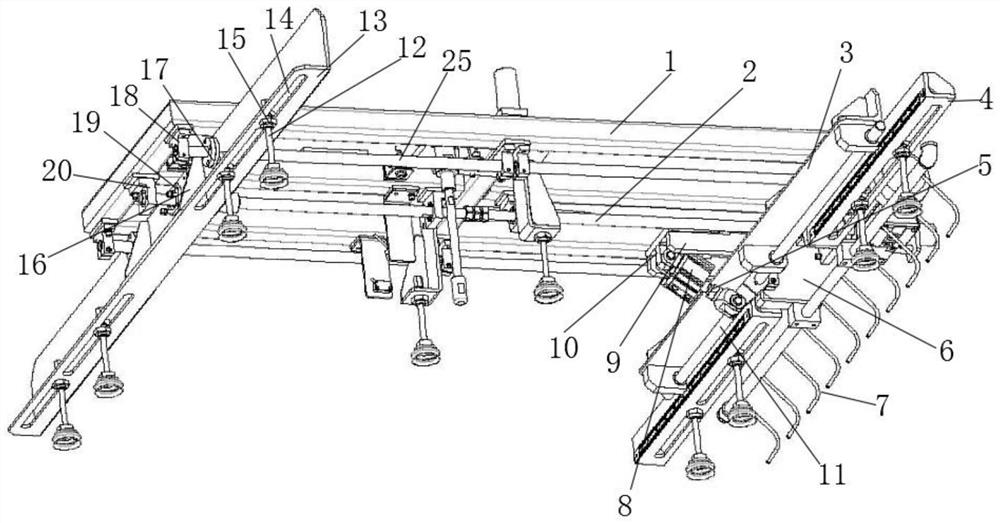
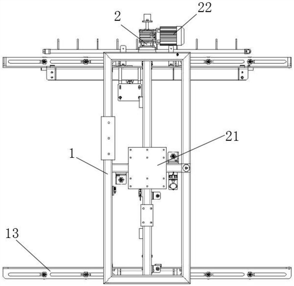
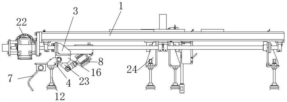
[0029] Such as Figure 1-4 As shown, a motor-driven automatic width-adjusting material suction device includes a fixed frame 1, two ends of the bottom surface of the fixed frame 1 are respectively fixed with two end seats 18, and the middle positions of the two ends of the bottom surface of the fixed frame 1 are set There are bearing housings 20, and a screw 2 is arranged between the two bearing housings 20. Limiting rods 25 are respectively arranged on both sides of the screw rod 2. The two ends of the limiting rods 25 are...


PUM


Abstract

The invention discloses a sucking device driven by a motor and capable of automatically regulating width. The sucking device comprises a fixed frame, wherein the two ends of the bottom surface of thefixed frame are fixedly provided with two end bases separately; the middle positions of the two ends of the bottom surface of the fixed frame are provided with bearing bases; a screw is arranged between the two bearing bases; the two sides of the screw are separately provided with limiting rods; and the two ends of each limiting rod are separately arranged on the end bases. A hydraulic rod pulsesthe fixed frame to move upwards, and a gas cylinder controls a piston rod inside to move towards the outer side and the inner side of a cylinder body in a circulating mode in an upward moving process,so that the piston rod drives the rotary rod to rotate back and forth, and a second placing plate rotates back and forth to form plate shaking; meanwhile, a gas blowing tube blows gas to plates, so that the gas enters the two plates to realize separating work of plates which are stuck together, and therefore, multiple plates are prevented from being sucked once during sucking, and follow-up processing of the plates is convenient.

Description

technical field [0001] The invention relates to the field of plate processing equipment, in particular to a motor-driven suction device with automatic width adjustment and a working method thereof. Background technique [0002] At present, plastic sheets are widely used, such as ABS or HIPS sheets used in refrigerator blister molding equipment or automotive interior molding equipment. During the processing of plastic sheets, suction devices are required. [0003] During the use of the existing material suction device, the same material suction device can only fixedly absorb a plate of a fixed size, and cannot adjust the position of the suction cup, and cannot meet the suction work of plates of different sizes, and the scope of application of the device is small; During the use of some suction devices, when the width is centered, it is necessary to manually move the plate for centering work, which is not convenient for the suction cup to absorb the plate, the centering effici...

Claims


Application Information

Patent Timeline
Patent Type & Authority Applications(China)
IPC IPC(8): B65G47/91B65G47/88
CPCB65G47/88B65G47/918
Inventor 杨闪闪葛孝华蒋军
Owner ANHUI KINGPOWER EQUIP & MOLD MFR
Why Eureka
Try Eureka