Third correction device of unwinding mechanism

A technology of deviation correction device and unwinding mechanism, which is applied in the direction of winding strips, structural parts, transportation and packaging, etc. It can solve the problems of increasing battery explosion, large deviation of appearance size, and inaccurate pole piece position, so as to avoid two The effect of secondary offset

Pending Publication Date: 2020-09-22
JIANGSU KATOP AUTOMATION CO LTD
View PDF0 Cites 0 Cited by
  • Summary
  • Abstract
  • Description
  • Claims
  • Application Information

AI Technical Summary

Problems solved by technology

[0004] The traditional die-cutting machine adopts a two-stage deviation correction mechanism, that is, the pole piece is corrected for the first time after the inflatable shaft unwinds, and the second deviation correction is carried out by using the traveling deviation correction at the middle position. After the second deviation correction, the pole piece is not directly It enters the mold for die-cutting, but enters the die-cutting machine after passing through a series of passing rollers or buffer rollers. Due to part processing errors and assembly errors in the passing rollers or buffer rollers, the position of the pole piece cannot be very accurate before entering the mold. Accurate, resulting in a large deviation in the appearance and size of the finished pole piece, increasing the risk of battery explosion, etc., so it needs to be improved

Method used


Image

  • Third correction device of unwinding mechanism
  • Third correction device of unwinding mechanism
  • Third correction device of unwinding mechanism

Examples


Embodiment Construction

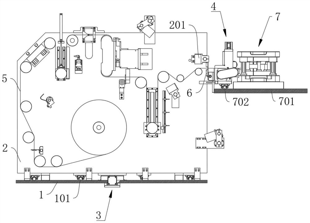
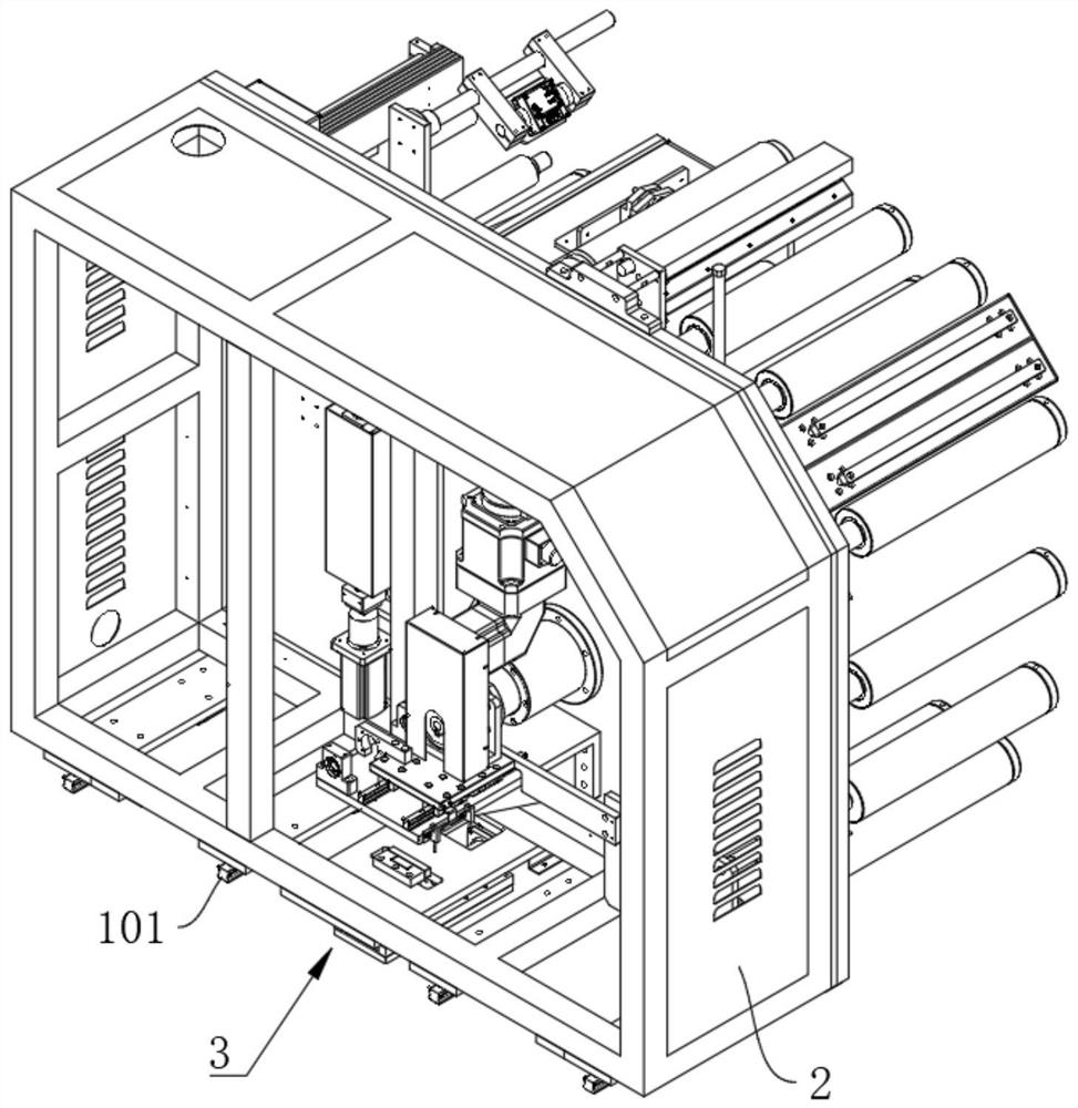
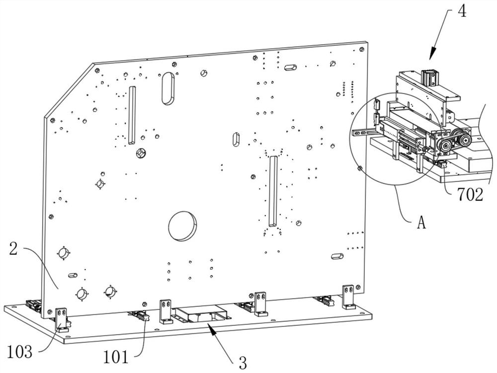
[0054] In the following, the concept, specific structure and technical effects of the present invention will be clearly and completely described in conjunction with the embodiments and the drawings to fully understand the purpose, features and effects of the present invention. Obviously, the described embodiments are only a part of the embodiments of the present invention, rather than all of them. Based on the embodiments of the present invention, other embodiments obtained by those skilled in the art without creative work belong to The scope of protection of the present invention. In addition, all the connection / connection relationships involved in the patent do not only refer to the direct connection of the components, but refer to the fact that a better connection structure can be formed by adding or reducing connection accessories according to specific implementation conditions. The various technical features in the invention can be combined interactively on the premise of ...


PUM


Abstract

The invention discloses a third correction device of an unwinding mechanism, and relates to an unwinding mechanism of a die-cutting machine. The device comprises a large board, an unwinding frame slidingly connected with the large board through a frame guide rail, a drive assembly arranged on the large board and used for driving the unwinding frame to move in the frame guide rail direction, a traction device connected with the unwinding frame, and a sensor; the traction device is used to clamp a pole piece and send the pole piece to a die-cutting mechanism with a die-cutting bottom plate, thedie-cutting bottom plate is provided with a traction guide rail parallel to the frame guide rail, and the traction device is slidingly connected with the traction guide rail; and the sensor is installed on the die-cutting bottom plate and is located on one side of the pole piece. The device solves the problems that the position of the pole piece cannot be very accurate before the pole piece entersa mold due to part machining errors and assembly errors of a pass roller or a snubber roll, resulting in large deviation in the appearance size of a finished pole piece and increasing of battery explosion and other risks.

Description

Technical field [0001] The invention relates to an unwinding mechanism of a die cutting machine, in particular to a third correction device of the unwinding mechanism. Background technique [0002] At present, the pole piece die cutting machine usually includes an unwinding mechanism and a die cutting mechanism, and the unwinding mechanism sends the pole piece to the die cutting mechanism at a certain speed for die cutting. [0003] The unwinding mechanism contains a variety of necessary devices such as tension adjustment devices and buffer devices. After the pole pieces pass through these devices and then enter the die-cutting mechanism, there will be a radial deviation along the direction of the unwinding roller. A correction device is added to the unwinding mechanism to correct the pole piece. [0004] The traditional die-cutting machine uses a secondary correction mechanism, that is, the pole piece is corrected for the first time after unwinding of the air expansion shaft, and t...

Claims


Application Information

Patent Timeline
IPC IPC(8): B65H16/00B65H23/02B65H20/02H01M4/04
CPCB65H16/00B65H20/02B65H23/0204B65H2701/11332H01M4/0409Y02E60/10
Inventor 徐世晶刘嘉兵
Owner JIANGSU KATOP AUTOMATION CO LTD
Why Eureka
Try Eureka