Automatic image correction system based on scanning

An automatic correction, image technology, applied in the conveyor control device, conveyor objects, object supply and other directions, can solve problems such as downtime, scanning image tilt, equipment paper jams, etc.

Active Publication Date: 2021-06-11
贵阳天海数码科技有限公司
View PDF16 Cites 0 Cited by
  • Summary
  • Abstract
  • Description
  • Claims
  • Application Information

AI Technical Summary

Problems solved by technology

[0004] Aiming at the deficiencies in the prior art, the technical problem solved by the present invention is to provide a scanning-based image automatic correction system to solve the problem that the existing scanning equipment shuts down due to the tilt of the scanned image and paper jams caused by paper offset during scanning.

Method used


Image

  • Automatic image correction system based on scanning
  • Automatic image correction system based on scanning
  • Automatic image correction system based on scanning

Examples


Embodiment Construction

[0019] The following is further described in detail through specific implementation methods:

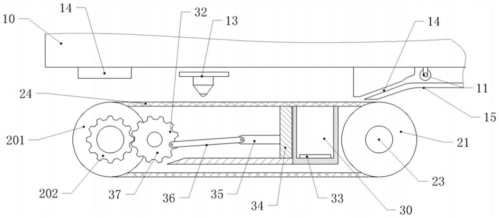
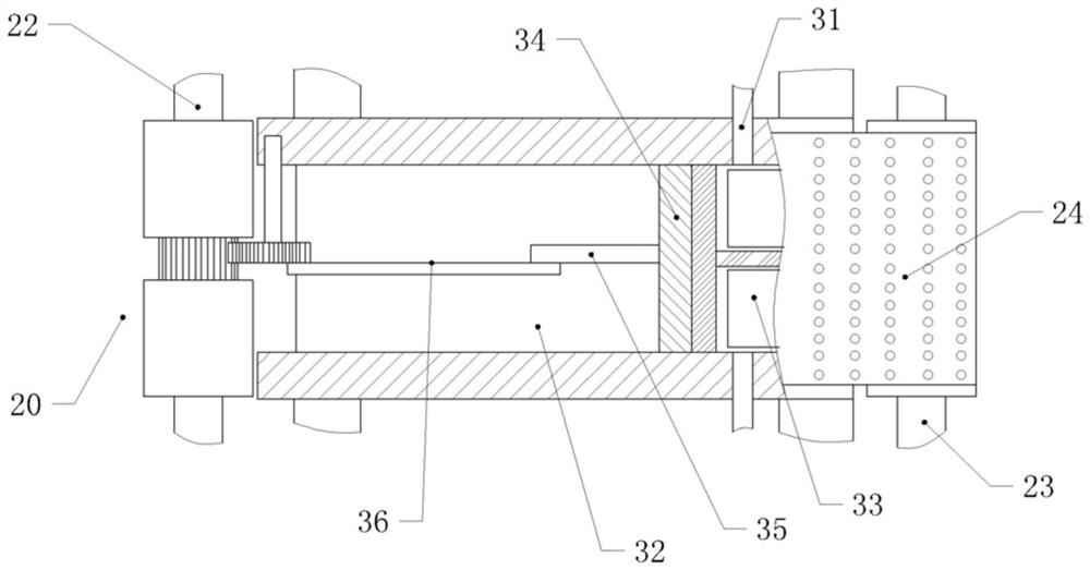
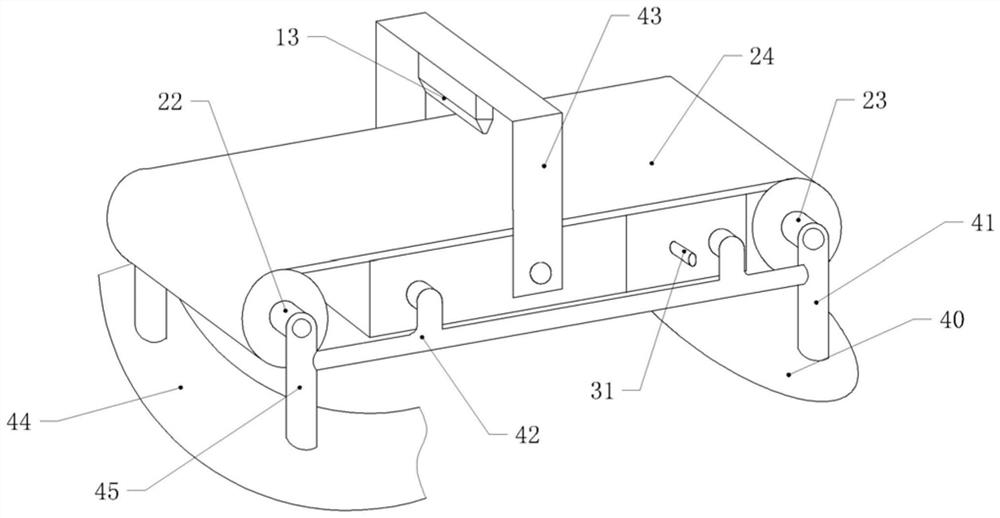
[0020] The reference numerals in the drawings of the description include: frame 10, paper feed wheel 11, paper feed channel 12, scanner 13, controller 14, horizontal platform 15, first rotating wheel 20, cylinder section 201, gear section 202 , the second rotating wheel 21, the first rotating shaft 22, the second rotating shaft 23, the conveyor belt 24, the negative pressure chamber 30, the air pipe 31, the sliding chamber 32, the pressure sensor 33, the slider 34, the swing lever 35, the connecting rod 36, the driving wheel 37. Turntable 40, first support bar 41, second support bar 42, support 43, slide rail 44, slide rail bar 45.

[0021] The embodiment is basically as attached figure 1 , figure 2 Shown:

[0022] A scan-based automatic image correction system includes a frame 10, a controller 14, a paper feeding mechanism and a scanning mechanism, and the scanning mechanism inc...


PUM


Abstract

The invention relates to the technical field of printing equipment, and particularly discloses an automatic image correction system based on scanning. The system comprises a rack, a controller, a paper feeding mechanism and a scanning mechanism, the paper feeding mechanism is located above a scanning machine, the scanning mechanism comprises a conveying device, a scanner, a deviation device and an adsorption mechanism, the scanner is arranged in the vertical direction, the tail of the scanner is connected with the rack, a transmission device is located below the scanner and rotationally connected with the rack, the transmission device comprises a conveying belt, a transmission wheel and a rotating shaft, the deviation device is connected with the rotating shaft in a sliding mode, a plurality of air holes are formed in the conveying belt, the adsorption mechanism is positioned in the transmission device, the adsorption mechanism comprises a negative pressure chamber arranged at one end close to the paper feeding mechanism, one end, away from the paper feeding mechanism, of the negative pressure chamber is provided with a sliding chamber, a sliding block connected with the sliding chamber in a sliding mode is arranged in the sliding chamber, and one side, away from the negative pressure chamber, of the sliding block is connected with a driving mechanism. The objective of the system is to solve the problem of scanning image inclination caused by paper offset during scanning of existing scanning equipment.

Description

technical field [0001] The invention relates to the technical field of printing equipment, in particular to an image automatic correction system based on scanning. Background technique [0002] With the advancement of the technology industry, various office machines such as scanners, printers, and fax machines have become indispensable equipment in modern offices. Among them, a printer with file scanning function or a separate scanner is the core equipment for digitizing office file data. [0003] When the scanning device is in use, the operator usually manually places the paper to be scanned on the pressure roller at the front entrance of the conveying channel of the scanning device. When the operator manually feeds the paper, there are differences and uncertainties in the human operation, and the superimposed paper The phenomenon of unevenness is more likely to occur. During the conveying process, the paper will have different degrees of lateral offset, which will cause t...

Claims


Application Information

Patent Timeline
Patent Type & Authority Applications(China)
IPC IPC(8): B65H5/22B65H5/06B65H7/02B65G41/00B65G43/08
CPCB65H5/224B65H5/06B65H7/02B65G41/007B65G43/08
Inventor 安进明
Owner 贵阳天海数码科技有限公司
Why Eureka
Try Eureka