Cell panel surface treatment device and process

A technology of surface treatment device and battery plate, applied in primary battery, device for coating liquid on the surface, surface pretreatment, etc., can solve the problems of inability to fix, the material is not neat enough, and the secondary deviation of the material, so as to avoid the second problem. The effect of the secondary offset

Inactive Publication Date: 2022-07-15
虞君莉
View PDF1 Cites 2 Cited by
  • Summary
  • Abstract
  • Description
  • Claims
  • Application Information

AI Technical Summary

Problems solved by technology

[0004] However, the above-mentioned existing technology has the following technical defects: 1. The materials required for the various components of the material foil are not limited before being laid and stacked, which may easily lead to the unevenness of the laid and stacked materials, thereby affecting the assembly effect of the material foil and product quality
[0005] 2. It is not possible to fix the materials required for each component of the material foil during the laying and stacking process, resulting in the secondary offset of the laid and stacked materials, making it difficult to align the materials
[0006] 3. The surface of the material required for each composition of the material foil is easy to attach dust and particles, which will affect the use effect of the battery board after production

Method used


Image

  • Cell panel surface treatment device and process
  • Cell panel surface treatment device and process
  • Cell panel surface treatment device and process

Examples


Embodiment 1

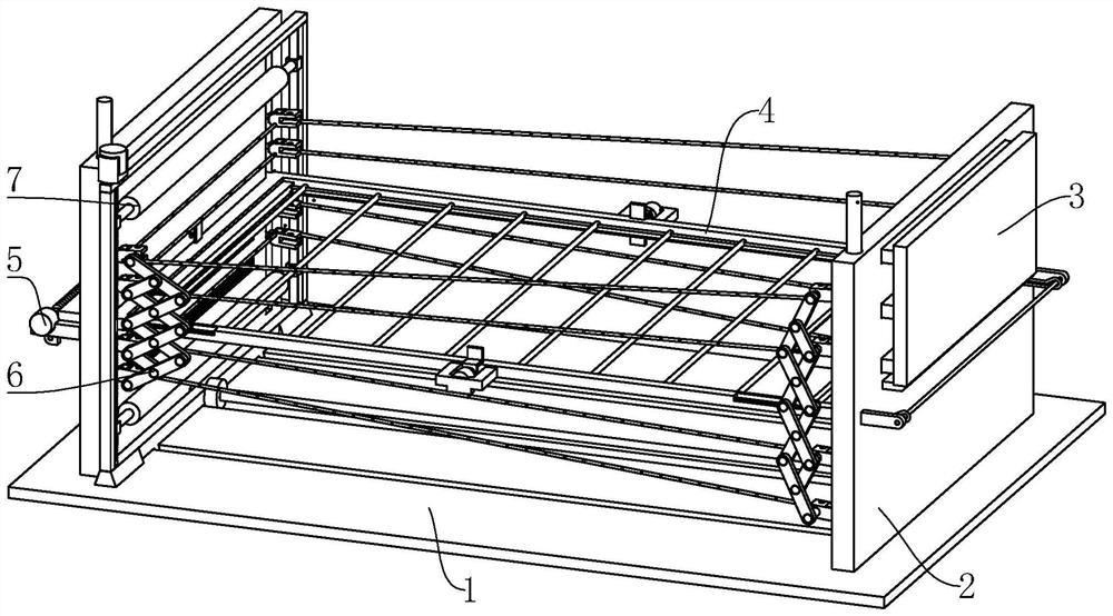
[0042] refer to figure 1 As shown, the battery plate surface treatment device includes a base 1 and a support plate 2 symmetrically arranged on the upper end of the base 1. The support plate 2 is provided with a blowing mechanism 3 for blowing and dusting the material foil raw materials, and a middle part of the support plate 2 is provided. There is a supporting frame 4 for supporting the battery plate, and a supporting mechanism 5 is arranged on the supporting frame 4. The supporting mechanism 5 can support the welded battery sheet, and the supporting plate 2 is located on the supporting frame 4. The left and right sides of the material foil are also provided with a clamping and gluing mechanism 6 for clamping the film-shaped raw materials of the material foil, and it can also be glued, because each film-shaped material of the material foil is stacked up and down. Therefore, the base 1 is provided with a pressing mechanism 7 for pressing the film-like constituent material of ...

Embodiment 2

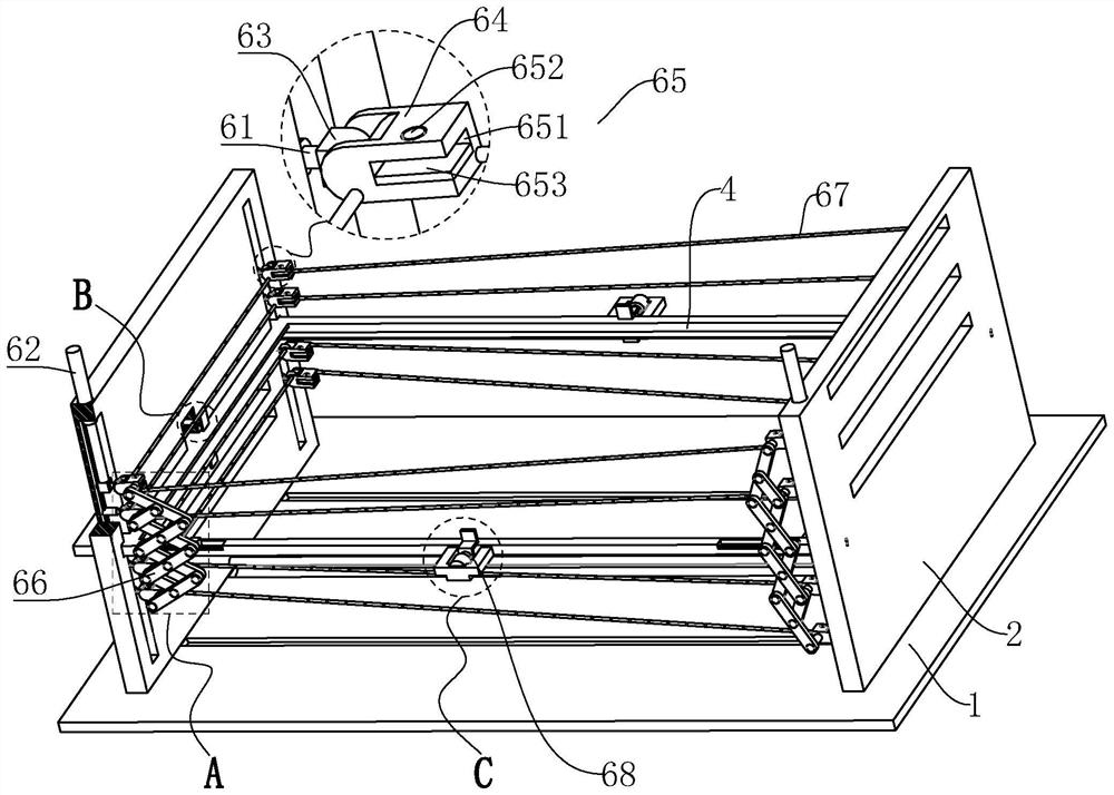
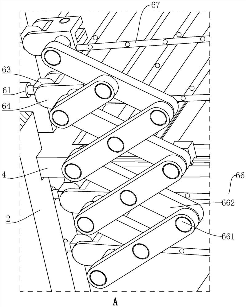
[0049] refer to image 3 As shown, on the basis of the first embodiment, in order to facilitate the adjustment of the position of the clamping blocks 64 so that the respective raw materials of the material foil can be attached to each other, a A scissor branch chain 66 that drives a plurality of clamping blocks 64 to move synchronously; specifically, the scissor branch chain 66 includes a pin shaft rod 661 arranged at the front end of the clamping block 64, and the outer surface of the pin shaft rod 661 is rotated and matched with The scissor rods 662 are stacked in the front and rear and are distributed in an X shape, and the middle parts of the scissor rods 662 on the front and rear sides and the other end of the scissor rods 662 are also rotated through the pin shaft 661. way to connect.

[0050] The pin shaft 661 corresponding to the position of the support frame 4 and close to the middle side of the support frame 4 is slidingly matched with the support frame 4 left and r...

Embodiment 3

[0054] refer to Figure 5As shown, on the basis of the second embodiment, in order to support the welded battery without affecting the bonding of the film-like constituent material of the material foil on the lower side of the battery with the battery, the supporting The frame 4 is provided with a supporting mechanism 5; specifically, the supporting mechanism 5 includes an installation side plate 51, a limit rod 52, an installation side block 53, a winding rod 54, a rotating motor 55, a fixed block 56, a connecting rope 57 and a bearing. The support rod 58, the right side of the right support plate 2 is provided with a front and rear symmetrical installation side plate 51, a limit rod 52 is arranged between the installation side plates 51 by means of rotation and cooperation, and the left support plate 2 is provided with A rectangular through slot, and the left end of the support frame 4 passes through the rectangular through slot and is located on the left side of the left su...


PUM


Abstract

The invention relates to a cell panel surface treatment device and process, the cell panel surface material foil assembling process adopts the following cell panel surface material foil assembling device, the cell panel surface material foil assembling device comprises a base, supporting plates are symmetrically arranged at the upper end of the base, and a blowing mechanism is arranged on the supporting plates; a bearing frame is installed between the middles of the supporting plates on the two sides, a bearing mechanism is arranged on the bearing frame, clamping and gluing mechanisms are arranged on the supporting plates and located on the left side and the right side of the bearing frame, and pressing mechanisms are arranged on the base and located on the upper side and the lower side of the bearing frame. According to the invention, the following technical defects in the prior art can be solved: materials are not limited before being laid and stacked, so that the laid materials are not tidy enough; materials cannot be fixed in the laying and stacking process, so that the laid materials are prone to secondary deviation; dust and particles attached to the surfaces of the materials can affect the using effect of the battery panel after production is completed.

Description

technical field [0001] The invention relates to the field of battery processing, in particular to a battery plate surface treatment device and process Background technique [0002] A battery refers to a part of the space of a cup, tank or other container or composite container that contains an electrolyte solution and metal electrodes to generate electric current, a device that can convert chemical energy into electrical energy, and has a positive electrode and a negative electrode. With the advancement of science and technology, batteries generally refer to small devices that can generate electrical energy, such as panels, solar cells, batteries, etc. [0003] The material foil on the surface of the battery board usually needs to be assembled with PTP, EVA, etc. after string welding and parallel welding during the production process. The corresponding ratio is accurate, and the Chinese patent publication number CN102157604A discloses a solar panel packaging material laying...

Claims


Application Information

Patent Timeline
Patent Type & Authority Applications(China)
IPC IPC(8): B05C9/10B05C13/02B05D3/04B08B5/02H01M6/00H01M10/04
CPCB05C9/10B05C13/02B05D3/0406B08B5/02H01M10/04H01M10/0404H01M10/0413H01M6/005
Inventor 虞君莉
Owner 虞君莉
Why Eureka
Try Eureka