Yarn breakage stopping device for loom

A technology for stopping device and loom, applied in looms, textiles, textiles and papermaking, etc., can solve the problems of unqualified knitted fabrics, lack of yarn in fabrics, broken spools, etc., so as to reduce the production rate of defective products, reduce The effect of production rate and quality assurance

Pending Publication Date: 2020-09-22
YANCHENG INST OF IND TECH
View PDF0 Cites 1 Cited by
  • Summary
  • Abstract
  • Description
  • Claims
  • Application Information

AI Technical Summary

Problems solved by technology

[0003] All the yarns on the loom are wound on bobbins, the bobbins are located behind and above the thread entry area, all the yarns are fed into the thread entry area at the same time, each thread is controlled by a separate needle, and the loom operates independently The yarn is automatically controlled by the thread-feeding area of ​​the loom. However, the spool is prone to thread breakage during the passive pay-off process. However, when a thread breakage occurs on a certain spool, the staff cannot be reminded in time. The loom is still running, and the woven fabric lacks the participation of yarn, resulting in unqualified woven fabrics, resulting in serious waste of raw materials, which cannot meet the needs of users

Method used


Image

  • Yarn breakage stopping device for loom
  • Yarn breakage stopping device for loom
  • Yarn breakage stopping device for loom

Examples


Embodiment Construction

[0022] The following will clearly and completely describe the technical solutions in the embodiments of the present invention with reference to the accompanying drawings in the embodiments of the present invention. Obviously, the described embodiments are only some, not all, embodiments of the present invention. Based on the embodiments of the present invention, all other embodiments obtained by persons of ordinary skill in the art without making creative efforts belong to the protection scope of the present invention.

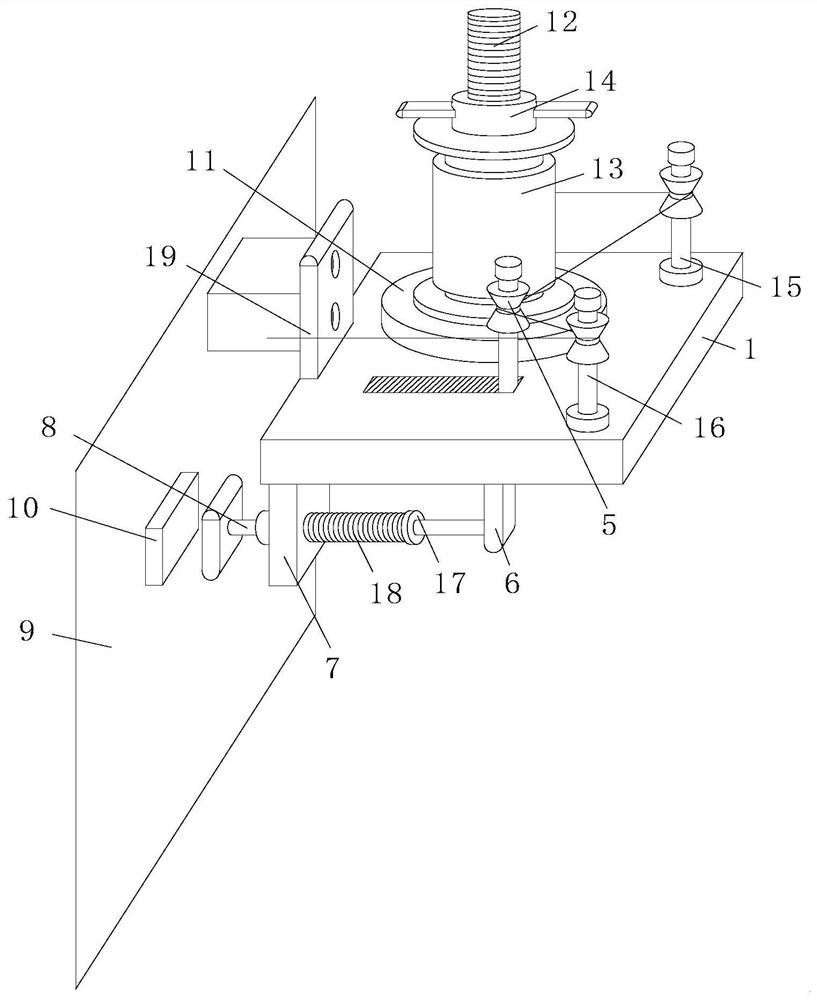
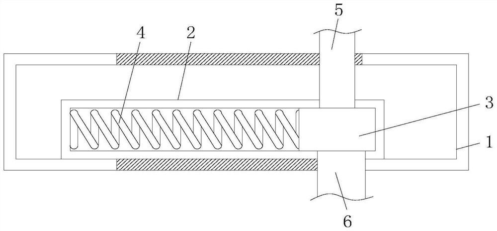
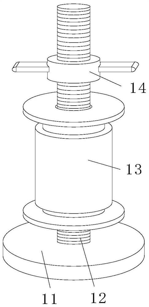
[0023] see Figure 1-3 , the present invention provides a technical solution: a yarn breakage stop device for a loom, including a mounting plate 1, a slide rail 2, a slider 3, a tension spring 4, a yarn guide wheel 5, a connecting plate 6, and a positioning plate 7. Push rod 8, loom 9, contact switch 10, turntable 11, screw mandrel 12, bobbin 13, fastener 14, first guide wheel 15, second guide wheel 16, limit ring 17, return spring 18 And connecting piece 19,...


PUM


Abstract

The invention relates to the technical field of looms, in particular to a yarn breakage stopping device for a loom. The yarn breakage stopping device comprises a mounting plate, a slide rail, a slideblock, a tension spring, yarn guide wheels, a connecting plate, a positioning plate, an ejector rod, the loom, a contact switch, a rotary table, a screw rod, a bobbin, a fastener, a first guide wheel,a second guide wheel, a limiting ring, a reset spring and a connecting piece; the front position of the bottom of the inner wall of the mounting plate is fixedly connected with the bottom of the slide rail; the slide block is slidably mounted in the slide rail; the tension spring is positioned inside the slide rail; and the two ends of the tension spring are respectively fixedly connected with the left side of the slide block and the left side of the inner wall of the slide rail. The yarn breakage stopping device for the loom in the invention achieves the purpose that the loom can automatically stop when a fed yarn is suddenly broken, a guarantee of playing a role of warning can be achieved when the yarn is broken, the loom is automatically turned off in a stop state, convenience is brought for workers to perform real-time processing, the quality of the woven fabric is ensured, and the generation rate of defective products is reduced.

Description

technical field [0001] The invention relates to the technical field of looms, in particular to a yarn breakage stop device for looms. Background technique [0002] The loom is the full name of a tool that processes raw materials such as thread, silk, and hemp into silk threads and then weaves them into cloth. Such as spinning pendants, spinning wheels, spindles, pedal looms, modern mechanical looms, modern numerically controlled automatic looms, etc. The development of ancient and modern textile processes and equipment is designed in response to textile raw materials. Therefore, raw materials play an important role in textile technology. [0003] All the yarns on the loom are wound on bobbins, the bobbins are located behind and above the thread entry area, all the yarns are fed into the thread entry area at the same time, each thread is controlled by a separate needle, and the loom operates independently The yarn is automatically controlled by the thread-feeding area of ​​...

Claims


Application Information

Patent Timeline
Patent Type & Authority Applications(China)
IPC IPC(8): D03D51/18
CPCD03D51/18
Inventor 周红涛武银飞周彬袁以华谢昊阳刘飞翔陆华李玉华吴含
Owner YANCHENG INST OF IND TECH
Why Eureka
Try Eureka