Anti-jamming open-type gate valve

An open-type, plug-in valve technology, applied in valve details, valve devices, sliding valves, etc., can solve problems such as affecting the service life of the plug-in valve, affecting the valve sealing effect, lack of open-type plug-in valve, etc., to ensure the work. Continuity, saving resources, improving usability

Active Publication Date: 2020-09-22
ZHEJIANG ZHONGHOU VALVE GRP CO LTD
View PDF6 Cites 7 Cited by
  • Summary
  • Abstract
  • Description
  • Claims
  • Application Information

AI Technical Summary

Problems solved by technology

[0003] During the closing and opening process, the valve seat and the valve plate are always in close contact with each other, so that the opening and closing force of the valve is stable, and it has the characteristics of cutting off the medium. However, when the open gate valve is used, when the valve is opened, there will be debris passing through the valve. , The accumulation of sundries adheres to the surface of the valve. With the increase of the service time of the valve, the sundries on the surface of the valve will accumulate more and more, which will block the valve, affect the sealing effect of the valve, and finally affect the service life of the gate valve. Therefore, there is a lack of a Anti-clogging open gate valve to increase the service life of the gate valve

Method used


Image

  • Anti-jamming open-type gate valve
  • Anti-jamming open-type gate valve
  • Anti-jamming open-type gate valve

Examples


Embodiment 1

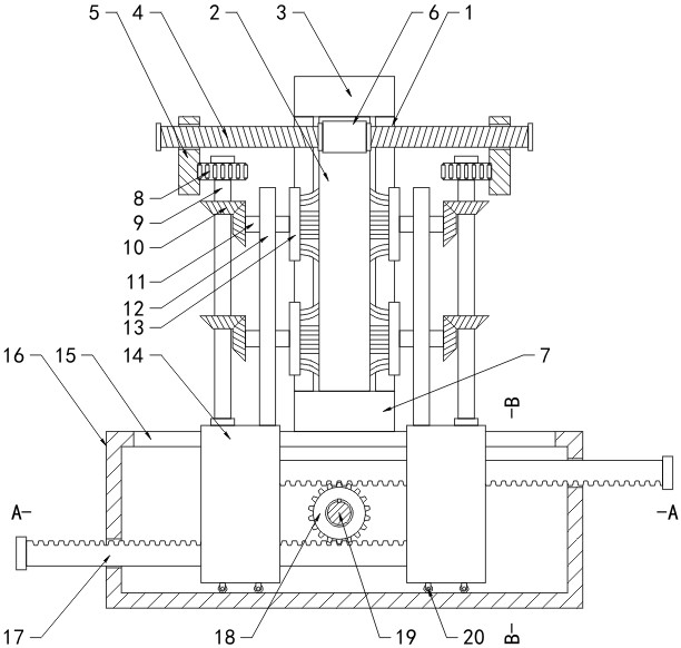
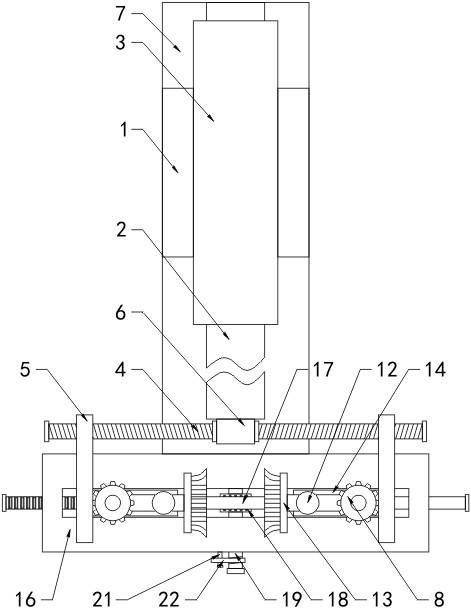
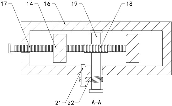
[0032] see Figure 1-5 , an anti-clogging open-type flapper valve, comprising a valve body 1 with a valve seat 7 at the bottom, a movable valve plate 2 inside the valve body 1 to realize the on-off of the valve body 1, and a valve body 1 on the top The driver 3 that drives the valve plate 2 to move, the side of the valve plate 2 close to the top is fixedly connected with the fixed block 6, and the two ends of the fixed block 6 are installed with the threaded rod 4 through the bearing rotation, and the fixed block 6 and the threaded rod 4 follow the valve plate 2 Synchronous movement, the first rack 5 is sleeved on the outside of the threaded rods 4 on both sides, the first rack 5 moves synchronously with the threaded rods 4, the side of the valve seat 7 is detachably connected to the adjustment box 16, and the top of the adjustment box 16 begins to have The chute 15 is slidingly connected with a symmetrically arranged and highly adapted slider 14 inside the chute 15, which is ...

Embodiment 2

[0034] The difference from Example 1 is that

[0035] see Figure 5 The outer wall of the second rotating shaft 11 and the inner surface wall of the bracket of the brush 13 are elastically connected by a spring 23. When the second rotating shaft 11 rotates, the brush 13 is driven to rotate, and the sundries on the valve plate 2 are cleaned. Falling, under the elastic effect of spring 23, hair brush 13 bounces up and down, cleans the sundries on valve plate 2 between hair brushes 13, improves the cleaning effect to valve plate 2.

Embodiment 3

[0037] The difference from Example 1 is that

[0038] see figure 1 with figure 2 , the first rack 5 and the threaded rod 4 are threadedly connected. During the adjustment of the distance between the brushes 13, the continuity of the transmission between the first rack 5 and the first gear 8 should also be ensured to control the first rack 5 and the first gear 8. A rack 5 does not rotate in the horizontal direction. By rotating the threaded rod 4, the position of the first rack 5 on the threaded rod 4 is adjusted according to the principle of thread transmission, so that the first rack 5 and the first gear 8 are always meshed. Transmission connection, wherein, when the threaded rod 4 rotates forward, the first rack 5 moves horizontally inward, and when it rotates reversely, the first rack 5 moves horizontally outward.


PUM


Abstract

The invention discloses an anti-jamming open-type gate valve. The gate valve comprises a valve body; a valve seat is arranged at the bottom of the valve body; a movable valve plate is arranged insidethe valve body and realizes opening and closing of the valve body; and a fixed block is fixedly connected with one side, near the top, of the valve plate. According to the gate valve, in the process that a driving member drives the valve plate to move back and forth in the valve body to realize opening/closing of the valve body, synchronous movement of a first rack and a valve door is realized viaconnection of the fixed block and a threaded rod, and under the action of a transmission system which is composed of a first gear, a first rotary shaft, a bevel gear and a second rotary shaft, rotation of a brush is realized; the rotating brush is in contact with the surface of the valve plate which moves relatively, and debris on the valve plate is cleaned, so the influence of overly stacked debris on the sealing effect and service life of the open-type gate valve is avoided; and at the same time, motion of the transmission system is realized by virtue of the driving member of the open-typegate valve, so use of other electrical driving devices is reduced, resources are saved and use cost is lowered.

Description

technical field [0001] The invention relates to the technical field of gate valves, in particular to an anti-clogging open gate valve. Background technique [0002] The flapper valve is also called the manual knife gate valve. The knife gate valve is a valve in which the valve plate and the valve body are always in close contact and sealed. The round opening on the valve plate is completely disengaged and matched with the diameter. The open gate valve is a kind of gate valve, which is made of nitrile rubber. It has good rigidity and compact structure. features. [0003] During the closing and opening process, the valve seat and the valve plate are always in close contact with each other, so that the opening and closing force of the valve is stable, and it has the characteristics of cutting off the medium. However, when the open gate valve is used, when the valve is opened, there will be debris passing through the valve. , The accumulation of sundries adheres to the surface...

Claims


Application Information

Patent Timeline
Patent Type & Authority Applications(China)
IPC IPC(8): F16K3/02F16K3/30F16K31/50F16K31/54B08B1/04
CPCF16K3/02F16K3/0254F16K3/0281F16K31/508F16K31/54B08B1/04B08B1/002
Inventor 项天津吴明祥秦小明朱阳章宇炫
Owner ZHEJIANG ZHONGHOU VALVE GRP CO LTD
Why Eureka
Try Eureka