Multimedia playing method and device, display control card and system and display system

A technology for multimedia playback and display control cards, applied in static indicators, instruments, etc., can solve the problem of inability to prevent video sources, and achieve the effect of avoiding illegal content playback and improving security and reliability.

Inactive Publication Date: 2020-09-22
XIAN NOVASTAR TECH
6 Cites 0 Cited by

AI-Extracted Technical Summary

Problems solved by technology

Therefore, the traditional playback control method cannot prevent the video source from being output from the operating system to the pro...

Abstract

The embodiment of the invention discloses a multimedia playing method, a multimedia playing device, a display control card, a display control system and a display system. The multimedia playing methodcomprises the following steps: analyzing pixel data at a specified position in an input image frame to serve as a first secret key; verifying the first secret key by utilizing a preset secret key soas to determine the legality of the input image frame; after the verification is passed, outputting the pixel data of the input image frame and the preset key in an associated manner. According to theembodiment of the invention, the situation that illegal content is played after a network hacker invades the multimedia playing device can be effectively avoided, and the safety and reliability of data transmission and display are improved.

Application Domain

Static indicating devices

Technology Topic

Data transmissionEngineering +4

Image

  • Multimedia playing method and device, display control card and system and display system
  • Multimedia playing method and device, display control card and system and display system
  • Multimedia playing method and device, display control card and system and display system

Examples

  • Experimental program(3)

Example

[0023] [First Embodiment]
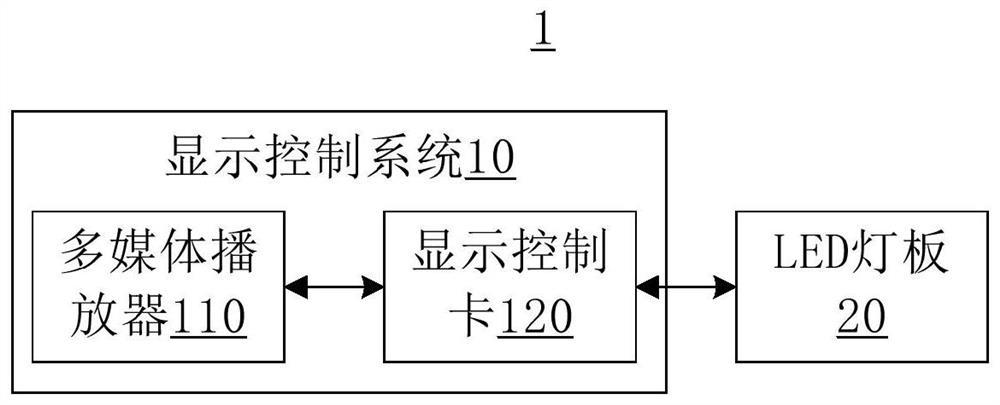
[0024] see figure 1 , which is a schematic structural diagram of a display system such as an LED display system provided by the second embodiment of the present invention. The display system 1 includes, for example, a display control system 10 and an LED light panel 20 connected to the display control system 10 .
[0025] Specifically, the display control system 10 here can be, for example, an LED display control system. The display control system 10 includes: a multimedia playback device (or a sending card, a multimedia player) 110 and a display control card (or a receiving card) 120 connected to the multimedia playback device 110 . The multimedia playback device 110 analyzes and processes the input video data and sends it to the display control card 120 .
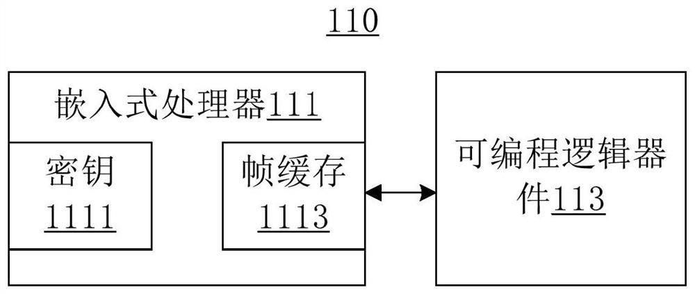
[0026] like figure 2 As shown, the multimedia playback device 110 includes, for example, an embedded processor 111 and a programmable logic device 113 connected to the embedded processor 111 . Embedded processor 111 includes frame buffer 1113 . On the embedded processor 111, for example, a key 1111 is stored in one of its registers. The key 1111 is generated by the screen configuration software of the host computer, such as LCT software, when the screen is configured, and is sent and solidified into the register of the embedded processor 111 . The key 1111 is, for example, data including four bytes. The frame buffer 1113 is used for buffering the pixel data of a frame of the image to be output in the input image data. The embedded processor 111 extracts one frame of pixel data of the target image frame from the input image data in the memory connected to the embedded processor 111 and puts it into the frame buffer 1113 to obtain the image frame to be output. like image 3 As shown, the size (resolution) of the image frame to be output is the size of the frame buffer 1113 . Therefore, generally, the size of the image frame to be output is larger than the size of the target image frame. The pixel data of a single pixel in the target image frame includes, for example, A, R, G, and B four channel data, A represents transparency data, R represents red color channel data, G represents green color channel data, and B represents blue color channel. data. The value range of each color channel data is 0 to 255. In addition, the embedded processor 111 also reads the key 1111 from the register, and uses the key 1111 as the pixel data of the specified position in the image frame to be output, that is, the four bytes of data of the key 1111 are respectively used as the pixel of the specified position data for the four channels of data. The specified position may be, for example, a pixel point in the image frame to be output in an area outside the target image frame, specifically, for example, the position of the lower left corner vertex in the image frame to be output. Of course, the specified position can also be the vertex position of the lower right corner in the image frame to be output. Then, the embedded processor 111 outputs the to-be-outputted image frame.
[0027] The programmable logic device 113 is, for example, an FPGA (Field-Programmable Gate Array, field programmable gate array), which is used for receiving and analyzing input image pixel data and outputting the analyzed image data. After receiving a first input image frame, the programmable logic device 113 first parses pixel data at a specified position in the first input image frame as a first key to be verified. Then, the first key to be verified is verified using the first verification key to determine whether the first input image frame is an image frame to be output output by the embedded processor 111 . The first verification key may be the key 1111 stored on the embedded processor 111 , or may be a key generated by the LCT software during screen configuration and solidified into the programmable logic device 113 , for example, a register thereof.
[0028]When the first key to be verified is inconsistent with the first verification key, the verification fails, indicating that the first input image frame is not the image frame to be output output by the embedded processor 111, and may be a hacker Intrusion and incoming illegal image data, at this time, the programmable logic device 113 stops outputting the pixel data of the first input image frame to the display control card 120 . When the first key to be verified is consistent with the first verification key, the verification is passed, indicating that the first input image frame is the to-be-output image frame output by the embedded processor 111, at this time programmable The logic device 113 places the first verification key in the field packet data. Field packet data is, for example, identification data representing the end of transmission of pixel data of the target image frame. One field packet data corresponds to one target image frame. Then the programmable logic device 113 will output the pixel data of the target image frame in the first input image frame of the to-be-output image frame and the second key in association with the output, specifically: after outputting the first input image frame After inputting the pixel data of the target image frame in the image frame, output field packet data corresponding to the target image frame and including the first verification key.
[0029] like Figure 4 As shown, the display control card 120 includes, for example, a microcontroller 121 and a programmable logic device 123 connected to the microcontroller 121 . The microcontroller 121 may be, for example, an MCU. A key 1231 is stored in a register of the programmable logic device 123 . The key 1231 is also generated by the screen configuration software of the host computer, such as LCT software, when the screen is configured, and is solidified into the register of the programmable logic device 123 . Here, the key 1111 is the same as the key 1231. After receiving a second input image frame and its corresponding field packet data, under the control of the microcontroller 121, the programmable logic device 123 parses the field packet data corresponding to the second input image frame to obtain the second input image frame. Key to be verified. The second key to be verified is verified using the key 1231 to determine the validity of the second input image frame.
[0030] When the second key to be verified is inconsistent with the key 1231, the verification fails, indicating that the second input image frame is not the image data output by the programmable logic device 113 of the multimedia playback device 110, and may be hacked and transmitted In this case, the programmable logic device 123 stops outputting the received pixel data of the second input image frame to the LED light panel 20 . When the second key to be verified is consistent with the key 1231, the verification is passed, indicating that the second input image frame is the image data output by the programmable logic device 113 of the multimedia playback device 110. At this time, the programmable logic device 123 The pixel data of the second input image frame is output to the light panel 20 for display.
[0031] It is worth mentioning here that the key 1111 and the key 1231 may also be different, but in the process of image data transmission, the key to be verified obtained by the corresponding processing of the key 1111 is consistent with the key 1231, thereby passing the verification.
[0032] To sum up, in the embodiment of the present invention, the verification key is pre-agreed and solidified on the multimedia playback device and the display control card during screen configuration, and then in the transmission process of the pixel data of the target image frame, the pixel at the specified position is used. The data transfer key and the pre-agreed verification key are used for two verifications to determine the legitimacy of the pixel data of the target image frame, that is, the comparison is performed at each link of the transmission process of the pixel data of the target image frame Verification ensures that the data displayed on the LED light board is the image data sent by its own multimedia playback device, which effectively avoids the occurrence of illegal content playback after network hackers invade the multimedia playback device, and improves the security and reliability of data transmission and display.

Example

[0033] [Second Embodiment]
[0034] see Figure 5 , which is a schematic flowchart of a multimedia playback method provided by the second embodiment of the present invention. The multimedia playback method according to the embodiment of the present invention mainly includes the steps:
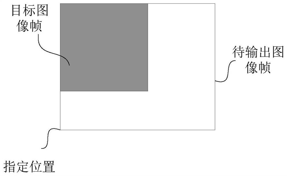
[0035] S11: Parse the specified position pixel data in the input image frame as the first key;
[0036] S13: Verify the first key with a preset key to determine the validity of the input image frame; and
[0037] S15: After the verification is passed, output the pixel data of the input image frame in association with the preset key.
[0038] For the specific implementation process and technical effects of the multimedia playback method in this embodiment, reference may be made to the description of the foregoing first embodiment, which will not be repeated here.

Example

[0039] [Third Embodiment]
[0040] see Image 6 , which is a schematic structural diagram of a multimedia playback device 300 according to the third embodiment of the present invention. The multimedia playback device 300 includes a parsing module 310 , a verification module 330 and an output module 350 .
[0041] The parsing module 310 is used for parsing the specified position pixel data in the input image frame as the first key;
[0042] a verification module 330, configured to verify the first key with a preset key to determine the validity of the input image frame; and
[0043] The output module 350 is configured to associate and output the pixel data of the input image frame and the preset key after the verification is passed.
[0044] Further, the parsing module 310, the verification module 330 and the output module 350 are integrated into the programmable logic device of the multimedia playback device.
[0045] For the specific working process and technical effect of the multimedia playback device 300 in this embodiment, reference may be made to the description of the foregoing first embodiment, which will not be repeated here.

PUM

no PUM

Description & Claims & Application Information

We can also present the details of the Description, Claims and Application information to help users get a comprehensive understanding of the technical details of the patent, such as background art, summary of invention, brief description of drawings, description of embodiments, and other original content. On the other hand, users can also determine the specific scope of protection of the technology through the list of claims; as well as understand the changes in the life cycle of the technology with the presentation of the patent timeline. Login to view more.

Similar technology patents

Access control method and system based on security tag

ActiveCN108270782AImprove safety and reliabilityAvoid Information Leakage
Owner:INST OF INFORMATION ENG CAS

Intelligent layered mining system applicable to offshore oilfield sand control well completion

InactiveCN106703763AStrong technical adaptabilityImprove safety and reliability
Owner:CHINA NAT OFFSHORE OIL CORP +1

Classification and recommendation of technical efficacy words

Why Eureka
Try Eureka