Inspection method and device for bottom of protective tube assembly and mating surface of nuclear fuel assembly
A nuclear fuel assembly and inspection method technology, applied in nuclear engineering, nuclear power generation, nuclear reactor monitoring, etc., can solve the problems of long hanging time of the reactor building and low inspection efficiency, and achieve improved inspection efficiency, fast moving speed, and simplified inspection devices Effect
- Summary
- Abstract
- Description
- Claims
- Application Information
AI Technical Summary
Problems solved by technology
Method used
Image
Examples
Embodiment 1
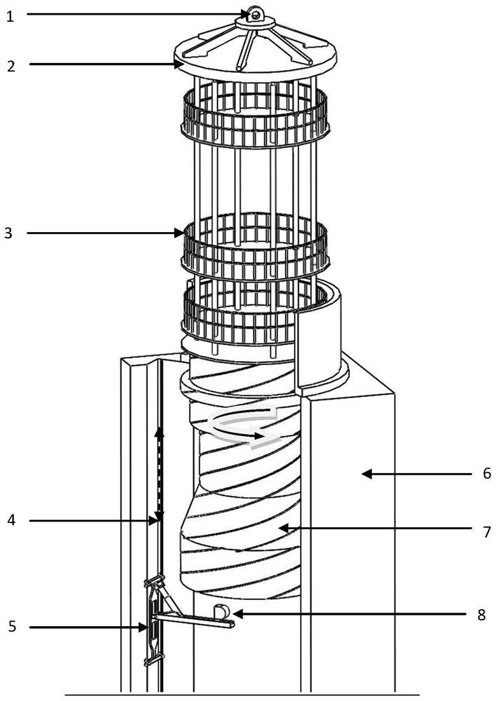
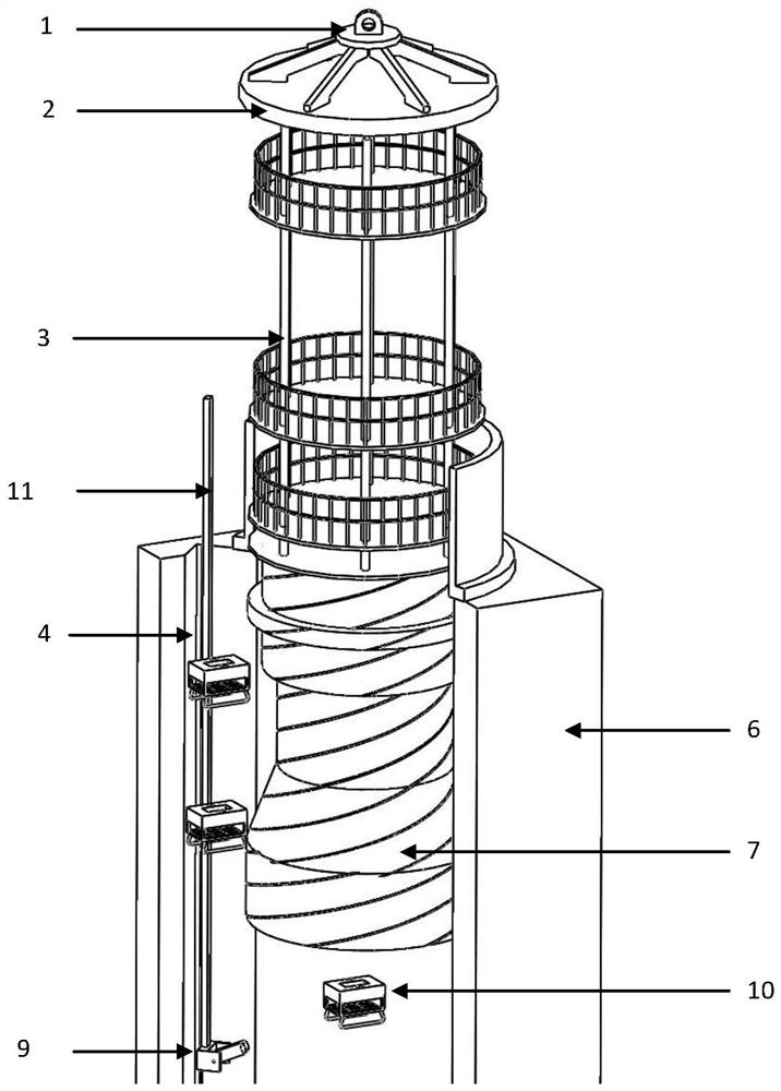
[0089] An inspection device for the mating surface between the bottom of the protection tube assembly and the nuclear fuel assembly, comprising: a lifting ring (1), an inspection well (6), a monitoring camera (9), and an automatic inspection device (10), the monitoring camera (9) is set At the bottom of the inspection well (6);
[0090] A guide rail (4) is provided on the side wall of the inspection well; the automatic inspection device (10) enters the inspection well along the guide rail (4);
[0091] The lifting ring (1) is arranged on the upper part of the inspection well (6), and is used for hanging the protection tube assembly (7) to be inspected.
Embodiment 2
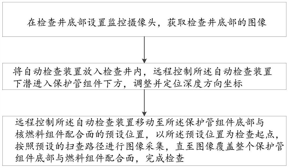
[0093] The flow chart of the inspection method in this embodiment can be found in Figure 4 .
[0094] (1) The automatic floating assembly adopts a frame-type shuttle structure, and its size is 572㎜×400㎜×565㎜. The inspection camera is an XRAD-PTZ type radiation-resistant camera, which is arranged vertically; the automatic floating assembly and the inspection The camera is assembled to form an automatic inspection device.
[0095] (2) Debugging the automatic inspection device.
[0096] (3) A monitoring camera is installed at the bottom of the inspection well to obtain images of the bottom of the inspection well.
[0097] (4) Put the automatic inspection device into the inspection well;
[0098] (5) Initially calibrate the inspection camera of the automatic inspection device by using a resolution calibration board.
[0099] (6) Remotely control the automatic inspection device to dive into the bottom of the protection tube assembly, adjust and locate the coordinates in the de...
Embodiment 3
[0110] (1) Set up a monitoring camera at the bottom of the inspection well to obtain images of the bottom of the inspection well.
[0111] (2) The automatic floating component adopts the frame-type shuttle structure, its size is 572㎜×400㎜×565㎜, and the inspection camera adopts XRAD-PTZ radiation-resistant camera, which is arranged vertically;
[0112] The automatic floating component is assembled with the inspection camera to form an automatic inspection device.
[0113] (3) Debugging the automatic inspection device.
[0114] (4) Put the automatic inspection device into the inspection well;
[0115] (5) Initially calibrate the inspection camera of the automatic inspection device by using a resolution calibration board.
[0116] (6) Remotely control the automatic inspection device to dive into the bottom of the protection tube assembly, adjust and locate the coordinates in the depth direction.
[0117] (7) Remotely control the movement of the automatic inspection device, and...
PUM
 Abstract
Description
Claims
Application Information
 - R&D
- Intellectual Property
- Life Sciences
- Materials
- Tech Scout
- Unparalleled Data Quality
- Higher Quality Content
- 60% Fewer Hallucinations
Browse by: Latest US Patents, China's latest patents, Technical Efficacy Thesaurus, Application Domain, Technology Topic, Popular Technical Reports.
© 2025 PatSnap. All rights reserved.Legal|Privacy policy|Modern Slavery Act Transparency Statement|Sitemap|About US| Contact US: help@patsnap.com


