Steel-cored aluminum strand crimping device

A technology of steel-cored aluminum stranded wire and crimping device, which is applied in the direction of connection, circuit/collector parts, electrical components, etc., to achieve the effect of convenient manufacture and use, reduction of investment, and convenience of simplicity

Active Publication Date: 2020-09-22
常熟市电力机具有限公司 +1
View PDF15 Cites 2 Cited by
  • Summary
  • Abstract
  • Description
  • Claims
  • Application Information

AI Technical Summary

Problems solved by technology

Since these patents, not limited to examples, also only use a single crimp, it is not sufficient to eliminate the aforementioned technical problems
[0007] Undoubtedly, the steel cores of the two steel-cored aluminum stranded wires, that is, the head and tail parts of the steel stranded core and the head and tail parts of the aluminum stranded wires, can be completely eliminated by the same device. There is no corresponding report in the patent and non-patent literature, and the technical solution to be introduced below is produced under this background

Method used


Image

  • Steel-cored aluminum strand crimping device
  • Steel-cored aluminum strand crimping device
  • Steel-cored aluminum strand crimping device

Examples


Embodiment Construction

[0026] In order to understand the technical essence and beneficial effects of the present invention more clearly, the applicant will describe in detail the following examples, but the descriptions of the examples are not intended to limit the solutions of the present invention. Equivalent transformations that are only formal but not substantive should be regarded as the scope of the technical solution of the present invention.

[0027] In the following descriptions, all concepts related to directionality or orientation of up, down, left, right, front and back are based on figure 1 The current position is a reference, so it cannot be understood as a special limitation on the technical solution provided by the present invention.

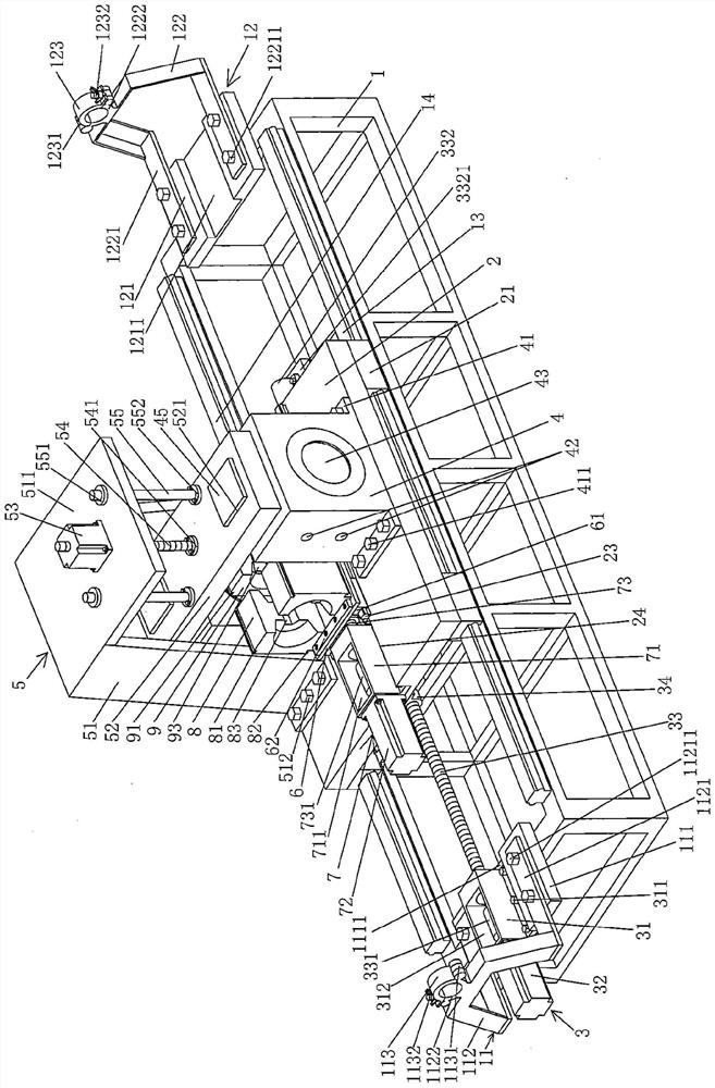
[0028] See figure 1 , shows a frame 1 that is hollowed out and has a rectangular frame structure (cuboid structure in this embodiment), and a first aluminum-steel strand clamping mechanism I11 is preferably fixed on the upper left end of the frame 1 b...


PUM


Abstract

Asteel-cored aluminum strand crimping device comprises a rack, a moving platform, a moving platform driving mechanism, apair of crimping die opening and closing cylinders, a pressing plate lifting mechanism, a die changing moving plate, adie changing moving plate driving mechanism and a pair of steel core stranded wire sleeve extrusion dies;a first steel-cored aluminum strand clamping mechanism isarranged at the upper part of the left end of the rack, and a second steel-cored aluminum strand clamping mechanism is arranged at the upper part of the right end of the rack; the moving platform isarranged at the upper part of the rack; the movingplatform driving mechanism is arranged on the first steel-cored aluminum strand clamping mechanism or the second steel-cored aluminum strand clampingmechanism and is connected with the movingplatform; the pair of crimping die opening and closing cylinders are arranged on the moving platform; the pressing plate lifting mechanism is fixed on the moving platform and corresponds to the tops of the pair of crimping die opening and closing cylinders; the die changing moving plate is arranged on the moving platform; the die changing moving plate driving mechanism is arranged on the moving platform and is connected with the die changing moving plate; the pair of steel core stranded wire sleeve extrusion dies is supported at the left end of the diechanging moving plate, and the pair of aluminum stranded wire sleeve extrusion dies is supported at the right end of the die changing moving plate. The dosage of equipment is reduced; the structure is simple and convenient to manufacture and use; a good secondary crimping effect is embodied, and the connection quality of the power transmission line is ensured; and the tensile strength of asteel core stranded wire at the joint is ensured.

Description

technical field [0001] The invention belongs to the technical field of power transmission line crimping tools, and in particular relates to a steel core aluminum stranded wire crimping device. Background technique [0002] From the terminology of the above-mentioned aluminum-steel-reinforced wire, it can be determined without a doubt that the center of the wire is the steel strand, and the outside of the wire is the aluminum strand that is enveloped outside the steel strand. Because the steel strand has high mechanical strength and strong tensile force, the steel strand is not suitable for power transmission, and because the mechanical strength and tensile force of the aluminum strand are not comparable to the steel strand, but the aluminum strand has The excellent electrical conductivity (small resistivity) and small specific gravity that steel strands cannot have, so the aforementioned steel-cored aluminum strands are widely used in high-power, high-power Voltage, long-di...

Claims


Application Information

Patent Timeline
Patent Type & Authority Applications(China)
IPC IPC(8): H01R43/048H01R43/052
CPCH01R43/048H01R43/052
Inventor 葛建华陈春明周志飞沈治沈建明
Owner 常熟市电力机具有限公司
Why Eureka
Try Eureka