
Closed-loop control method and system for magnetizing state of variable-flux permanent magnet motor

A permanent magnet motor, closed-loop control technology, applied in control systems, low-speed motor control, AC motor control, etc., can solve the problem of inability to effectively track the magnetization state, observation and control errors of the magnetization state, and the reduction of the observation accuracy of the magnetization state, etc. problems, to achieve the effect of expanding the application speed range, reducing the difficulty of system configuration, and reducing the effect of cross saturation

Inactive Publication Date: 2020-09-22
HUAZHONG UNIV OF SCI & TECH
View PDF11 Cites 8 Cited by
  • Summary
  • Abstract
  • Description
  • Claims
  • Application Information

AI Technical Summary

Problems solved by technology

The observer method has the problem of convergence speed. When the charging and demagnetization speed is close to the convergence speed of the observer, the magnetization state obtained by the observer will not be able to effectively track the actual motor magnetization state, resulting in errors in observation and magnetization state control.
[0009] In addition, the observation methods adopted in Document 1 and Document 2 are developed based on the back EMF of the motor. Therefore, when the motor operates in the low speed range, it is limited by the low back EMF and the dead zone effect of the power electronic inverter. The magnetic state observation accuracy is significantly reduced

Method used


Image

  • Closed-loop control method and system for magnetizing state of variable-flux permanent magnet motor
  • Closed-loop control method and system for magnetizing state of variable-flux permanent magnet motor
  • Closed-loop control method and system for magnetizing state of variable-flux permanent magnet motor

Examples


Embodiment Construction

[0039] In order to make the object, technical solution and advantages of the present invention clearer, the present invention will be further described in detail below in conjunction with the accompanying drawings and embodiments. It should be understood that the specific embodiments described here are only used to explain the present invention, not to limit the present invention. In addition, the technical features involved in the various embodiments of the present invention described below can be combined with each other as long as they do not constitute a conflict with each other.

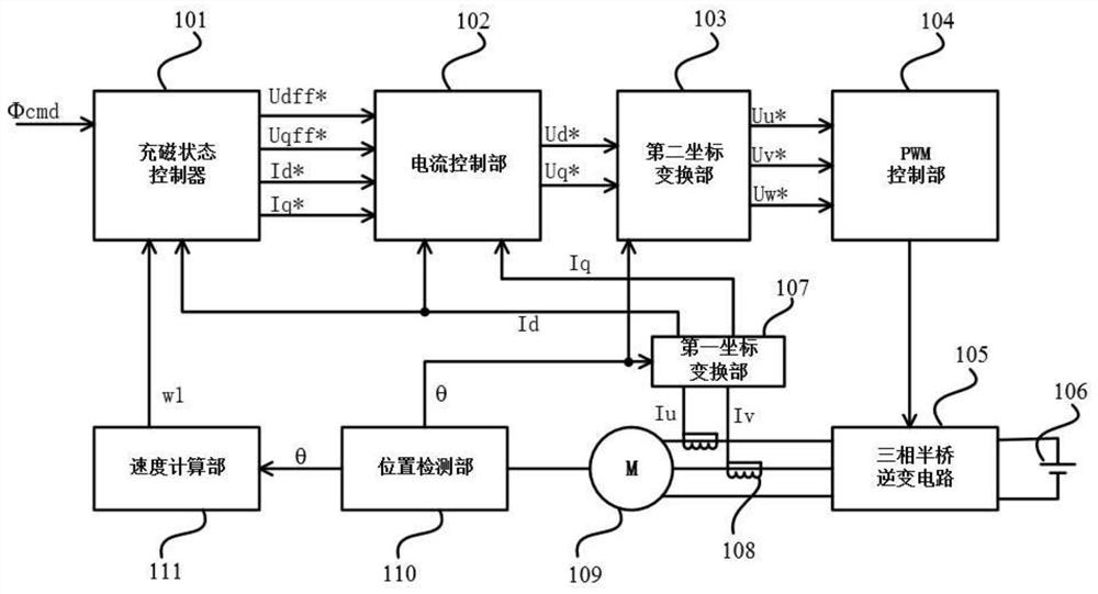
[0040] Embodiments of the present invention provide a method for closed-loop control of the magnetization state of a variable flux permanent magnet motor on the one hand, including the following steps:

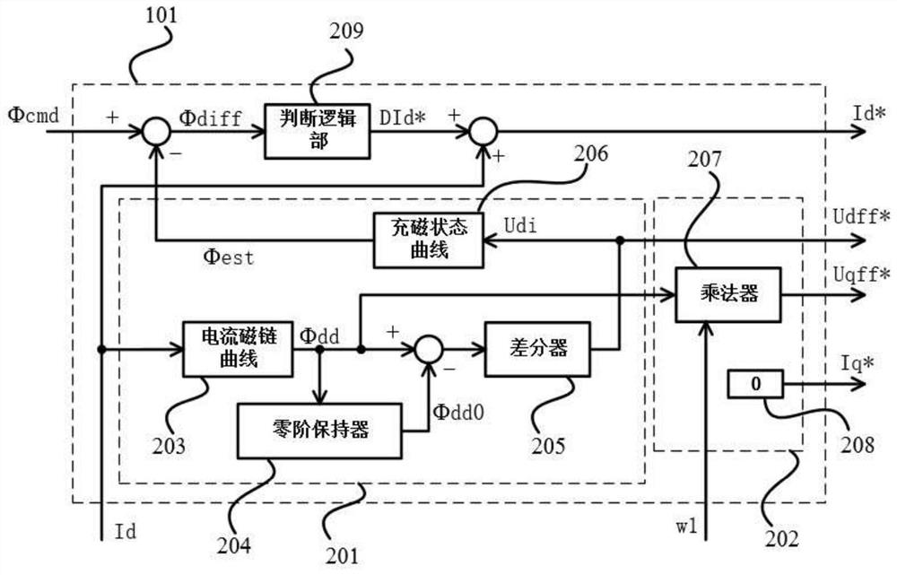
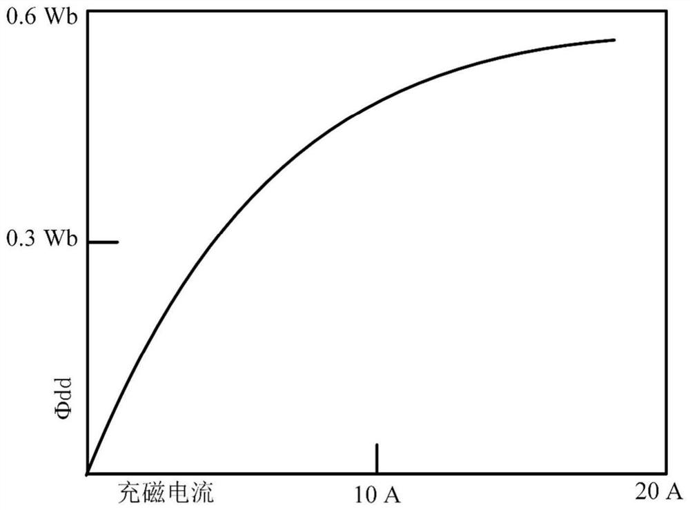
[0041] Detect the d-axis current feedback value and use the current flux linkage curve to obtain the d-axis armature flux linkage, and calculate the change of the d-axis armature flux linkage in...


PUM


Abstract

The invention discloses a closed-loop control method and system for the magnetizing state of a variable-flux permanent magnet motor, and belongs to the field of driving control of variable-flux permanent magnet motors. The method comprises the steps of firstly, detecting a d-axis current feedback value, obtaining a d-axis armature flux linkage by utilizing a current flux linkage curve, and calculating the change of the d-axis armature flux linkage in combination with the d-axis armature flux linkage of the previous control period so as to obtain an induced voltage Udi; obtaining a magnetizingstate estimated value [phi]est by utilizing the induced voltage Udi based on a relation curve between the induced voltage and the magnetizing state; and then carrying out error comparison on a magnetizing state instruction [phi]cmd and the magnetizing state estimated value [phi]est, then generating a d-axis current instruction difference value through logic judgment, and then updating a d-axis current instruction Id* for carrying out current closed-loop control. According to the invention, the magnetizing state is estimated based on the induced voltage change generated by the d-axis current inthe magnetizing and demagnetizing process, and a voltage decoupler is introduced, so that the magnetizing state of the motor can be accurately controlled under the static and rotating states of the variable-flux permanent magnet motor.

Description

technical field [0001] The invention belongs to the field of drive control of variable flux permanent magnet motors, and more specifically relates to a closed-loop control method and system for the magnetization state of variable flux permanent magnet motors. Background technique [0002] The variable flux permanent magnet motor is used to improve the overall efficiency of the traditional permanent magnet motor in the field of speed control drive applications. Traditional permanent magnet motors use high-coercivity permanent magnets, and the magnetization state of the motor cannot be changed after the magnetization of the permanent magnets is completed. When the traditional permanent magnet motor runs in the high-speed range, the voltage at the motor terminal exceeds the DC bus voltage. Therefore, it is necessary to continuously inject a field-weakening current on the d-axis of the motor's rotating coordinate system to offset the back EMF voltage that increases with the spee...

Claims


Application Information

Patent Timeline
Patent Type & Authority Applications(China)
IPC IPC(8): H02P23/03H02P23/14H01F13/00H02P27/08
CPCH01F13/003H02P23/03H02P23/14H02P27/08
Inventor 陈俊桦曲荣海
Owner HUAZHONG UNIV OF SCI & TECH
Learn More