
Electromechanical equipment control cabinet

A technology of electromechanical equipment and control cabinets, which is applied in the direction of electrical equipment shells/cabinets/drawers, electrical equipment structural parts, casings/cabinets/drawer parts, etc., which can solve the problem of slow heat dissipation, inconvenient use, and heat dissipation effects Not good and other problems, to achieve a good cooling effect and ensure the stability

Inactive Publication Date: 2020-09-22
南京亚页防护设备制造有限公司
View PDF4 Cites 0 Cited by
  • Summary
  • Abstract
  • Description
  • Claims
  • Application Information

AI Technical Summary

Problems solved by technology

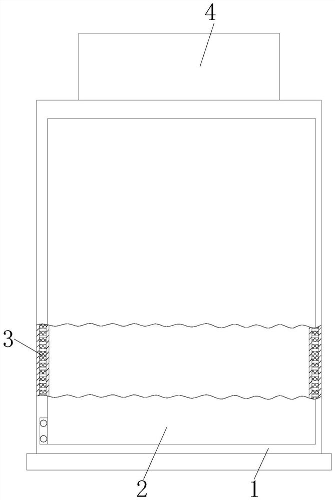
[0004] Aiming at the deficiencies of the prior art, the present invention provides an electromechanical equipment control cabinet, which has the advantage of good heat dissipation effect, and solves the problem that the existing electromechanical equipment control cabinet has poor heat dissipation effect when in use, and often the heat dissipation devices in the cabinet are fixed so that the heat dissipation effect is slow, so it is not convenient for people to use

Method used


Image

  • Electromechanical equipment control cabinet
  • Electromechanical equipment control cabinet
  • Electromechanical equipment control cabinet

Examples


Embodiment Construction

[0021] The following will clearly and completely describe the technical solutions in the embodiments of the present invention with reference to the accompanying drawings in the embodiments of the present invention. Obviously, the described embodiments are only some, not all, embodiments of the present invention. Based on the embodiments of the present invention, all other embodiments obtained by persons of ordinary skill in the art without making creative efforts belong to the protection scope of the present invention.

[0022] In the description of the invention, it should be noted that the terms "upper", "lower", "inner", "outer", "front end", "rear end", "both ends", "one end", "another end" etc. The indicated orientation or positional relationship is based on the orientation or positional relationship shown in the drawings, and is only for the convenience of describing the present invention and simplifying the description, rather than indicating or implying that the referre...


PUM


Abstract

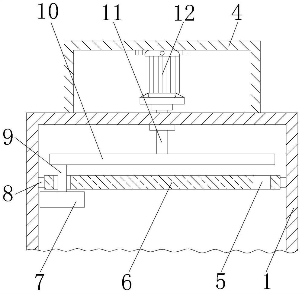
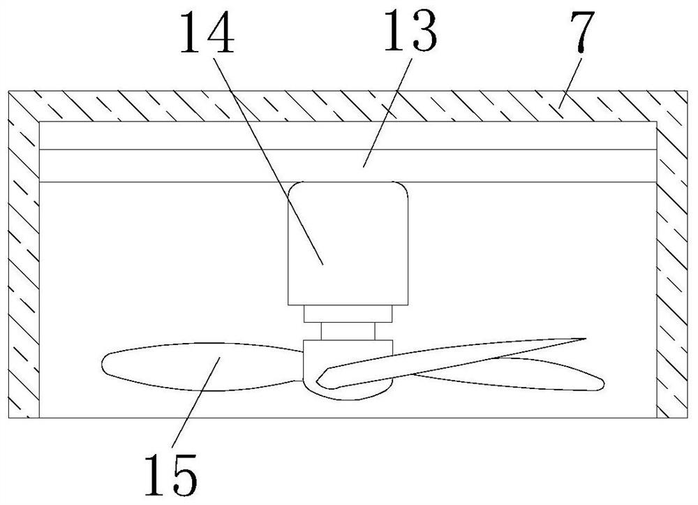
The invention discloses an electromechanical equipment control cabinet. The cabinet comprises a cabinet body, wherein the front side of the cabinet body is movably connected with a box door through ahinge; punching nets are installed at the bottoms of the two sides of the inner wall of the cabinet body, a fixed plate is installed at the top of the inner wall of the cabinet body, a transmission box is fixedly connected to the top of the cabinet body, a servo motor is fixedly connected to the top of the inner wall of the transmission box, and a rotating shaft is fixedly connected to the outputend of the servo motor. According to the invention, the servo motor drives the rotating shaft to rotate, the rotating shaft drives a rotary table to rotate, and the rotary table drives the sliding rodto slide in the circular sliding chute; the sliding rod drives a heat dissipation box to rotate; the heat dissipation box rotates to dissipate heat in the cabinet body in a larger range, thereby achieving the good heat dissipation effect, and solving the problems that the heat dissipation effect is slow, and people cannot use the cabinet conveniently because an existing electromechanical equipment control cabinet is poor in heat dissipation effect in use and a heat dissipation device in the cabinet is always fixed.

Description

technical field [0001] The invention relates to the technical field of electromechanical equipment, in particular to a control cabinet for electromechanical equipment. Background technique [0002] Electromechanical equipment generally refers to machinery, electrical appliances, and electrical automation equipment. In construction, it refers to the collective name of machinery and pipeline equipment other than geotechnical, carpentry, steel bars, and muddy water. It is different from hardware and refers to finished products that can achieve certain functions. Electromechanical equipment needs to use control cabinets, but the existing electromechanical equipment control cabinets do not have a good heat dissipation effect during use. Often the cooling devices in the cabinets are fixed, so that the heat dissipation effect is slow, so it is not convenient for people to use. Contents of the invention [0003] (1) Solved technical problems [0004] Aiming at the deficiencies of...

Claims


Application Information

Patent Timeline
IPC IPC(8): H05K5/02H05K7/14H05K7/18H05K7/20
CPCH05K5/0217H05K7/14H05K7/18H05K7/20136H05K7/20181
Inventor 严磊张颖严学刚
Owner 南京亚页防护设备制造有限公司
Learn More