Pipe cutting device for machining

A pipe cutting and machining technology, applied in metal processing equipment, shearing machine equipment, pipe cutting devices, etc., can solve the problems of increased human labor, low cutting efficiency, etc., and achieves a high degree of automation, high cutting efficiency, and continuous cutting. Effect

Inactive Publication Date: 2020-09-25
刘彩
View PDF0 Cites 4 Cited by
  • Summary
  • Abstract
  • Description
  • Claims
  • Application Information

AI Technical Summary

Problems solved by technology

[0002] In the process of mechanical processing, sometimes it is necessary to cut off the long pipe according to the required length. At present, most of the cutting of the pipe is to place the long pipe on the support, and use the cutting mechanism attached to the support to cut the long pipe. However, When this cutting method cuts off a long pipe, it is necessary to manually adjust the remaining long pipe to the bottom of the cutting mechanism, which makes the cutting efficiency relatively low, and at the same time strengthens the human labor.

Method used


Image

  • Pipe cutting device for machining
  • Pipe cutting device for machining
  • Pipe cutting device for machining

Examples


Embodiment 1

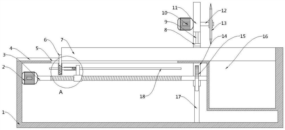
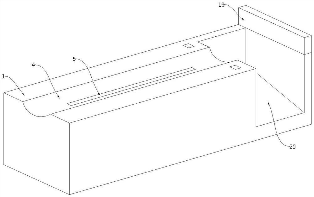
[0025] see Figure 1-4 , this embodiment provides a pipe cutting equipment for mechanical processing, including a bottom box 1, a cutting assembly arranged on the upper part of the bottom box 1, a pusher assembly 6 arranged on one side of the cutting assembly, and a Inside the bottom box 1 is a driving assembly for driving the pusher assembly 6 to move towards the cutting assembly. A baffle 19 is fixedly arranged on the side of the cutting assembly away from the pusher assembly 6. Specifically, the cutting assembly includes Movable plate 11, the second motor 10 that is fixedly arranged on the movable plate 11 towards the pusher assembly 6 side and the cutting wheel 13 that is arranged on the movable plate 11 away from the pusher assembly 6 side, the output end of the second motor 10 is fixedly connected The rotating shaft 12, the end of the rotating shaft 12 away from the second motor 10 passes through the movable plate 11 and is fixedly connected with the cutting wheel 13, th...

Embodiment 2

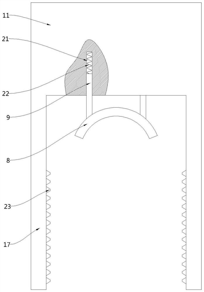
[0038] see figure 1 and image 3 , a pipe cutting device for mechanical processing. Compared with Embodiment 1, this embodiment is provided with a pressing plate 8 under the movable plate 11, a connecting rod 9 is fixedly installed on the upper part of the movable plate 8, and a connecting rod 9 is fixed at the bottom of the movable plate 11 There is a concave hole 21 , the upper end of the connecting rod 9 extends to the inside of the concave hole 21 and is fixedly connected with a first elastic body 22 , and the end of the first elastic body 22 away from the connecting rod 9 is fixedly connected with the bottom of the concave hole 21 .

[0039] When the driving half gear 15 drives the movable plate 11 to move downward through the drive rod 14, the movable plate 11 drives the pressure plate 8 to move downward, thereby using the pressure plate 8 to compress the pipeline 7 to prevent the pipeline 7 from being caused by the rotational force generated during cutting. Rocking occ...


PUM


Abstract

The invention provides a pipe cutting device for machining, and belongs to the technical field of machining. The pipe cutting device comprises a bottom box, a cutting assembly arranged on the upper part of the bottom box, a material pushing assembly arranged on one side of the cutting assembly, and a driving assembly arranged inside the bottom box and used for driving the material pushing assemblyto move towards the cutting assembly. In an embodiment of the invention, a to-be-cut pipe is placed on the upper part of the bottom box, and a movable plate is driven to move downwards by virtue of the operation of the driving assembly so as to drive a second motor, a rotating shaft and a cutting wheel to move downwards; the cutting wheel is utilized to cut the pipe; after the first cutting of the pipe, the driving assembly is utilized to drive the material pushing assembly to move towards the cutting assembly so as to push the pipe for the next cutting; and the continuous cutting of the pipecan be realized by reciprocation. The pipe cutting device for machining has the advantages of high cutting efficiency and high automation degree.

Description

technical field [0001] The invention belongs to the technical field of mechanical processing, in particular to a pipe cutting device for mechanical processing. Background technique [0002] In the process of mechanical processing, sometimes it is necessary to cut the long pipe according to the required length. At present, most of the cutting of the pipe is to place the long pipe on the support, and use the cutting mechanism attached to the support to cut the long pipe. However, When this cutting method cuts off the long pipe once, the remaining long pipe needs to be manually adjusted to the lower part of the cutting mechanism, which makes the cutting efficiency relatively low, and meanwhile increases the labor force. Contents of the invention [0003] In view of the above-mentioned deficiencies in the prior art, the technical problem to be solved by the embodiments of the present invention is to provide a pipe cutting device for mechanical processing. [0004] In order to...

Claims


Application Information

Patent Timeline
Patent Type & Authority Applications(China)
IPC IPC(8): B23D21/00B23D33/00
CPCB23D21/00B23D33/00
Inventor 刘彩
Owner 刘彩
Why Eureka
Try Eureka