Pipeline inner wall derusting device

A pipeline and inner cavity technology, which is applied in the field of rust removal devices on the inner wall of pipelines, can solve the problems of affecting the working distance, slipping, and insufficient traction of the inner wall rust removal device, and achieve the effect of improving rust removal efficiency and reducing friction

Inactive Publication Date: 2020-09-25
缪静
View PDF10 Cites 12 Cited by
  • Summary
  • Abstract
  • Description
  • Claims
  • Application Information

AI Technical Summary

Problems solved by technology

[0002] In recent years, with the rapid development of transportation, industry, agriculture and construction, the pipeline transportation system is used in all aspects of civil and industry, and people pay more and more attention to the utilization of pipeline transportation technology. It has obvious advantages, but because the materials transported in the pipe travel through the pipe for a long time, and due to the influence of chemical corrosion inside the pipe and factors outside the pipe, rust will inevitably appear on the bottom of the pipe and on the pipe wall, and the rust attached to the pipe wall is to a large extent It hinders the smooth passage of transport materials. At present, some inner wall derusting devices have insufficient traction, which seriously affects the working distance; and due to the influence of the working environment, slipping often occurs. For some pipes with a lot of rust on the pipe wall, the derusting effect is not good. Affect the long-term effective use of the pipeline, so a kind of rust removal device for the inner wall of the pipeline is designed and produced here to solve the above problems

Method used


Image

  • Pipeline inner wall derusting device
  • Pipeline inner wall derusting device
  • Pipeline inner wall derusting device

Examples


Embodiment 1

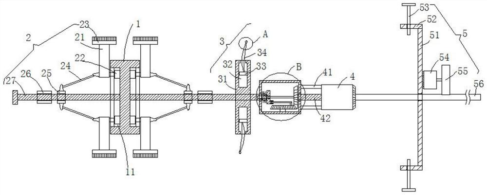
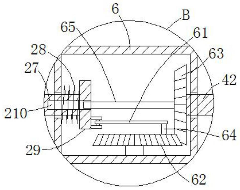
[0025] see Figure 1-3 , this embodiment provides a pipeline inner wall derusting device, including a fixing mechanism 5, a drive motor 4, a connecting seat 1, and two symmetrical derusting mechanisms 2 centered on the connecting seat 1, and the fixing mechanism 5 includes a fixing plate 51. Two positioning plates 52, a transmission motor 54 and a threaded transmission rod 56, the center position of the right end face of the driving motor 4 is rotationally connected with the left end of the threaded transmission rod 56, and the left end face of the driving motor 4 is connected with an inner cavity through two connecting rods 41 It is a hollow box 6 with a hollow structure. The drive motor 4 rotates through the right end surface of the hollow box 6 through the power shaft 42, and is connected with the first bevel gear 63 located in the inner cavity of the hollow box 6. The front side wall of the hollow box 6 The second bevel gear 62 is rotatably connected with the pin shaft. Th...

Embodiment 2

[0034] see Figure 1-3 , further improvements have been made on the basis of Example 1:

[0035] The rectangular rod outer wall of the threaded rod 27 of the right side derusting mechanism 2 slides and sleeves the spring 28 between the limit block 29 and the left end face of the hollow box 6 inner cavity, by setting the spring 28, the threaded rod of the right side derusting mechanism 2 When the rectangular rod 27 slides along the inner cavity of the hollow box 6, the impact force between the limit block 29 and the left end surface of the inner cavity of the hollow box 6 is reduced.


PUM


Abstract

The invention discloses a pipeline inner wall derusting device. The pipeline inner wall derusting device comprises a fixing mechanism, a driving motor, a connection seat and two bilaterally-symmetrical derusting mechanisms with the connection seat as a center; the fixing mechanism comprises a fixing plate, two positioning plates, a conveying motor and a threaded conveying rod; the center positionof the right end surface of the driving motor is rotationally connected with the left end of the threaded conveying rod, the left end surface of the driving motor is connected with a hollow box with an inner cavity being of a hollow structure through two connection rods, the driving motor rotationally penetrates through the right end surface of the hollow box through a power shaft and is connectedwith a first bevel gear located in the inner cavity of the hollow box, and the side wall of the front side of the inner cavity of the hollow box is rotationally connected with a second bevel gear through a hinge pin; and the two derusting mechanisms each comprise a threaded rod, a threaded sleeve, a sliding sleeve, a plurality of adjusting blocks annularly and uniformly distributed at intervals,and a plurality of cleaning hairbrushes annularly and uniformly distributed at intervals. The pipeline inner wall derusting device can adapt to pipelines different in opening diameter conveniently, quickly conduct feeding and derusting and blow away removed iron rust.

Description

technical field [0001] The invention relates to the related technical field of derusting the inner wall of a pipeline, in particular to a derusting device for the inner wall of a pipeline. Background technique [0002] In recent years, with the rapid development of transportation, industry, agriculture and construction, the pipeline transportation system is used in all aspects of civil and industry, and people pay more and more attention to the utilization of pipeline transportation technology. It has obvious advantages, but because the materials transported in the pipe travel through the pipe for a long time, and due to the influence of chemical corrosion inside the pipe and factors outside the pipe, rust will inevitably appear on the bottom of the pipe and on the pipe wall, and the rust attached to the pipe wall is to a large extent It hinders the smooth passage of transport materials. At present, some inner wall derusting devices have insufficient traction, which seriousl...

Claims


Application Information

Patent Timeline
Patent Type & Authority Applications(China)
IPC IPC(8): B24B27/033B24B5/40B24B55/06B24B27/00B24B41/04B24B47/12
CPCB24B5/40B24B27/0076B24B27/033B24B41/04B24B47/12B24B55/06
Inventor 缪静
Owner 缪静
Why Eureka
Try Eureka