Supercharge Your Innovation With Domain-Expert AI Agents!

Electrode stem lifting device of electroslag furnace

A technology of lifting device and electrode rod, which is applied in the field of electroslag furnace, can solve problems such as the decline of steel ingot quality and difficult temperature control, and achieve the effects of prolonging service life, high working efficiency and improving structural stability

Inactive Publication Date: 2020-09-25
JIANGYOU ZHONGXIN SPECIAL METAL MATERIAL CO LTD
View PDF7 Cites 0 Cited by
  • Summary
  • Abstract
  • Description
  • Claims
  • Application Information

AI Technical Summary

Problems solved by technology

[0006] In order to solve the problem that the electroslag furnace electrode rod lifting device in the prior art uses two sets of mechanisms to switch the consumable electrodes to work, resulting in temperature changes during the switching process, it is difficult to control the temperature at the same level as before, so that the production To solve the problem of the decline in the quality of steel ingots, a lifting device for the electrode rod of the electroslag furnace is provided

Method used


Image

  • Electrode stem lifting device of electroslag furnace
  • Electrode stem lifting device of electroslag furnace
  • Electrode stem lifting device of electroslag furnace

Examples


Embodiment 1

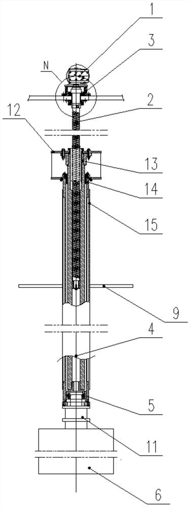
[0024] An electroslag furnace electrode rod lifting device, including a driving motor 1, is characterized in that the driving motor 1 is connected with a lead screw 2 arranged in the vertical direction, the top of the lead screw 2 is sleeved with a bearing support 3, and the screw The bottom end of the lever screw 2 is connected with an electrode rod 4, and a thrust bearing is connected between the bearing support 3 and the lead screw 2. The electrode rod 4 includes an inner ring rod 13, a middle ring rod 14 and an outer ring rod 15 from the inside to the outside. , The bottom end of the electrode rod 4 is connected with a pneumatic chuck 5, the pneumatic chuck 5 is installed between the inner ring rod 13 and the outer ring rod 15, and the pneumatic chuck 5 is connected with the consumable electrode 6.

[0025] The production structure adopts a single self-consumable electrode 6 up and down. On the one hand, the step of switching electrodes is omitted. The whole production proc...

Embodiment 2

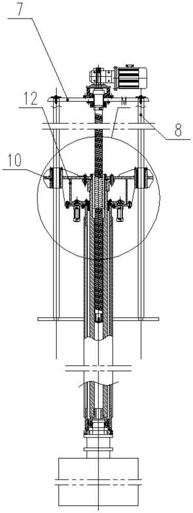
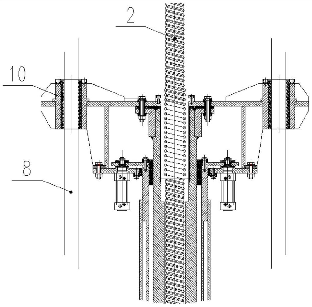
[0027] On the basis of Embodiment 1, both sides of the bearing support 3 are connected with an upper horizontal strut 7, and the upper horizontal strut 7 is connected with a guide rod 8 arranged parallel to the lead screw 2, and the bottom end of the guide rod 8 A lower horizontal strut 9 is connected, the lower horizontal strut 9 is connected with the electrode rod 4, the upper end of the electrode rod 4 is connected with a guide sleeve 10 set on the guide rod 8, and the lower horizontal strut 9 is connected to the outer ring rod 15 , The guide sleeve 10 is connected with the inner ring rod 13 .

[0028] Preferably, a sealing washer is connected between the upper horizontal strut 7 and the bearing support 3 .

[0029] Through the two symmetrical guide rods 8 and the guide sleeve 10 matched with the guide rods 8, it is ensured that the consumable electrode 6 moves up and down stably along the set direction during the lifting process, which facilitates the precise docking with ...

Embodiment 3

[0031] On the basis of Embodiment 1, a conductive electrode 11 is connected between the consumable electrode 6 and the pneumatic chuck 5, the upper end of the conductive electrode 11 is installed in the pneumatic chuck 5, and the lower end of the conductive electrode 11 is connected to the consumable electrode 6. Fixed connection. The conductive electrode 11 that is only used for conduction separates the consumable electrode 6 from the pneumatic chuck 5 by a certain distance, thereby avoiding damage to the pneumatic chuck 5 due to long-term exposure to high temperature, and prolonging the service life of the device.


PUM


Abstract

The invention discloses an electrode stem lifting device of an electroslag furnace, belongs to the technical field of electroslag furnaces, and solves the problem that in the prior art, two groups ofmechanisms are adopted to switch consumable electrodes to work, so that the temperature is difficult to control at a constant level, and the quality level of produced steel ingots is reduced. The electrode stem lifting device comprises a driving motor, the driving motor is connected with a lead screw arranged in the vertical direction, the top end of the lead screw is sleeved with a bearing support, the bottom end of the lead screw is connected with an electrode stem, a thrust bearing is connected between the bearing support and the lead screw, and the electrode stem comprises an inner ring stem, a middle ring stem and an outer ring stem from inside to outside; and the bottom end of the electrode stem is connected with a pneumatic chuck, and the pneumatic chuck is installed between the inner ring stem and the outer ring stem and connected with the consumable electrodes. According to the electrode stem lifting device, the step of electrode switching is omitted, the whole production process is continuously carried out, power failures are not needed, the temperature is constant, the texture uniformity of the steel ingots is effectively guaranteed, and the product quality is improved.

Description

technical field [0001] The invention belongs to the technical field of electroslag furnaces, and in particular relates to a lifting device for an electrode rod of an electroslag furnace. Background technique [0002] With the rapid development of the world's industry, the manufacturing industry has higher and higher requirements for the stability of metal materials. Since electroslag metallurgy was proposed in the 1940s, electroslag metallurgy technology has a series of advantages, such as excellent metal properties (high purity, fine structure, smooth surface), economical rationality (simple equipment , convenient operation, lower production cost than vacuum arc remelting, high metal yield), and stable, flexible and controllable process, electroslag metallurgy has developed rapidly in countries all over the world. It is applied to various fields, including aviation, aerospace, electronics, and atomic energy. [0003] Electroslag furnace is a kind of special smelting equip...

Claims


Application Information

Patent Timeline
Patent Type & Authority Applications(China)
IPC IPC(8): C22B9/187
CPCC22B9/18
Inventor 朱云辉孙建国张旭东付豪全亮
Owner JIANGYOU ZHONGXIN SPECIAL METAL MATERIAL CO LTD
Features
  • R&D
  • Intellectual Property
  • Life Sciences
  • Materials
  • Tech Scout
  • Unparalleled Data Quality
  • Higher Quality Content
  • 60% Fewer Hallucinations
Learn More