
A tile automatic laying trolley

A technology of automatic laying and tiles, which is applied in the direction of construction and building construction, can solve the problems of potential safety hazards, tile throwing, tile waste, etc., and achieve the effect of low cost, high efficiency, simple and reliable equipment

Active Publication Date: 2021-11-23
SHANDONG INST FOR PROD QUALITY INSPECTION
View PDF17 Cites 0 Cited by
  • Summary
  • Abstract
  • Description
  • Claims
  • Application Information

AI Technical Summary

Problems solved by technology

[0003] The existing tile laying machine comprises a main frame with a tile placement platform on the upper part, a construction frame at the bottom of the main frame, a lifting frame on one side of the main frame, a rotating arm hinged on the lifting frame, and the free movement of the rotating arm There is a vacuum suction cup on the end, and the displacement of the tiles can be changed through multiple rotations of the rotating arm. Because the tiles are pneumatically adsorbed, under the action of centrifugal force, the tiles are easily thrown out during rotation, resulting in waste of tiles. Security risks

Method used


Image

  • A tile automatic laying trolley
  • A tile automatic laying trolley
  • A tile automatic laying trolley

Examples


Embodiment Construction

[0028] The present invention will be further explained below in conjunction with the accompanying drawings.

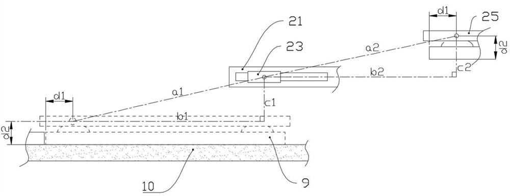
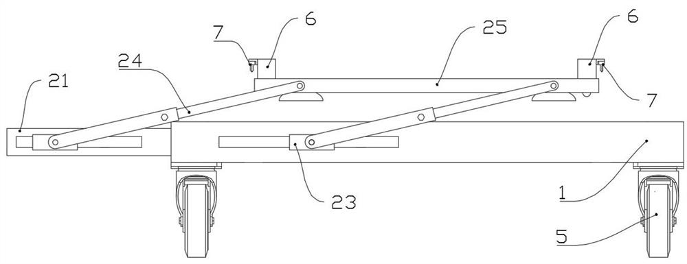
[0029] This embodiment is an automatic tile laying trolley, including a vehicle frame 1 and a gripping mechanism for placing tiles 9 to the laying position; the gripping mechanism includes a horizontally arranged upper suction plate 25 and two pull rods 21, The lower plane of the upper suction plate 25 is provided with several suction cups 26 for sucking the ceramic tiles 9, and the drawing rod 21 is horizontally drawable and installed on opposite sides of the vehicle frame 1;

[0030] The pull rod 21 and the vehicle frame 1 on the corresponding side are provided with chute 22 , and a motor I 23 is adjustablely installed in each chute 22 . The specific structure is that a slide block is arranged in the chute 22, the motor I23 is fixed on the slide block, and a knob bolt is arranged on the slide block to adjust the position of the slide block. The structure is simple, a...


PUM


Abstract

The invention belongs to automation equipment, which is an automatic tile laying trolley, which includes a frame and a grabbing mechanism for placing tiles to a laying position; the grabbing mechanism includes a horizontally arranged upper suction plate and a pair of pull rods. The lower plane of the upper suction plate is provided with several suction cups for absorbing tiles. The draw rods can be drawn horizontally and installed on opposite sides of the frame. Two motors I are installed on the draw rods, and the motors I The rotating shafts are respectively connected to one end of two swing rods one by one, and the other end of each swing rod is hinged on the side of the upper suction plate, and the two swing rods are arranged in parallel; The two swing rods driven by the two motors I one by one and the upper suction plate together form a parallelogram motion mechanism. The trolley can realize the laying under the premise of keeping the tiles in a horizontal state, which is convenient and quick, and will not damage the tiles.

Description

technical field [0001] The invention relates to automation equipment technology, in particular to a ceramic tile automatic laying trolley. Background technique [0002] The tile laying of building floors and slabs is done manually. Manual laying needs to be laid out first, and then aligned, moved closer and compacted one by one. The labor intensity is high, the construction efficiency is low, and the technical requirements for the operator are high. . In order to simplify the ceramic tile laying process and reduce the labor intensity of the operator, there have been special equipment for tile laying. [0003] The existing tile laying machine comprises a main frame with a tile placement platform on the upper part, a construction frame at the bottom of the main frame, a lifting frame on one side of the main frame, a rotating arm hinged on the lifting frame, and the free movement of the rotating arm There is a vacuum suction cup on the end, and the displacement of the tiles c...

Claims


Application Information

Patent Timeline
Patent Type & Authority Patents(China)
IPC IPC(8): E04F21/22
CPCE04F21/22
Inventor 于晓阳刘娜娜孙建宇马洪涛崔岩于航海陈全旺
Owner SHANDONG INST FOR PROD QUALITY INSPECTION
Learn More