Electric tailgate driving system and control method

A drive system and tailgate technology, which is applied to doors, door/window accessories, power control mechanisms, etc., can solve the problems of difficult electric tailgate products, difficult installation, and low cost performance, so as to facilitate heat dissipation and waterproof, improve The effect of stability and convenient assembly

Pending Publication Date: 2020-09-25
武汉辰沃科技有限公司
View PDF9 Cites 2 Cited by
  • Summary
  • Abstract
  • Description
  • Claims
  • Application Information

AI Technical Summary

Problems solved by technology

However, the bottleneck problem of the current 2 drive rods plus 1 ECU control solution is high cost, low cost performance and difficult installation, which makes it difficult for electric tailgate products to become the standard configuration of automobiles like electric window regulators.

Method used


Image

  • Electric tailgate driving system and control method
  • Electric tailgate driving system and control method
  • Electric tailgate driving system and control method

Examples


Embodiment 1

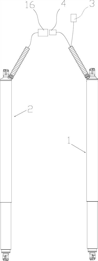
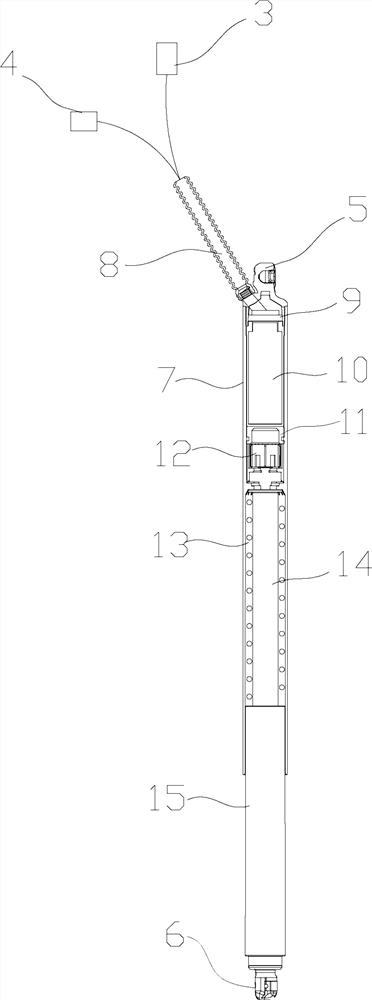
[0048] An electric tailgate driving system, which includes an electronically controlled balance bar 1 and a driving bar 2, and an ECU module 10 is arranged in the electronically controlled balance bar 1;

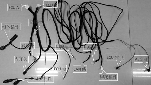
[0049]A wire harness connector 3 is also provided, and the wire harness connector 3 is electrically connected to the ECU module 10 through the wire harness. The wire harness connector 3 is used to connect the vehicle controller to receive instructions and power input from the vehicle controller; Commands are delivered via CAN or CAN FD protocol.

[0050] The electronically controlled balance bar 1 is connected to the driving bar 2 through a wire harness, the ECU module 10 is used to drive the driving bar 2 to move, and the electronically controlled stabilizing bar 1 moves along with the driving bar 2 . With this structure, the combination of the driving rod 2 and the electronically controlled balance rod 1 is used to expand the installation space of the ECU module 10, and th...

Embodiment 2

[0073] A control method using the above electric tailgate drive system, comprising the following steps:

[0074] S1. The vehicle controller sends an opening or closing command to the ECU module 10;

[0075] The opening or closing command includes the activation of the driving rod 2, the control of the rotation direction, the speed adjustment, the opening angle or the stroke command;

[0076] S2. The ECU 10 converts the opening or closing command into a PWM control command of the Hall motor 17, and the PWM control command includes starting, rotation direction control, speed adjustment, opening angle or stroke command of the Hall motor 17;

[0077] When approaching the two ends of the stroke of the driving rod 2, the speed of the Hall motor 17 is relatively slow, and the corresponding speed of opening and closing of the door becomes slow;

[0078] When the driving rod 2 is in the middle of the stroke, the Hall motor 17 rotates relatively fast, so as to shorten the time used for...


PUM


Abstract

The invention provides an electric tailgate driving system and a control method. An ECU (Electronic Control Unit) module is arranged in an electric control balance bar; a harness connector is also provided; the harness connector is electrically connected with the ECU module through a harness, and is used for connecting a vehicle control unit to receive instructions and power input of the vehicle control unit; the electronic control balance bar is connected with a driving bar through a wire harness; the ECU module is used for driving the driving bar to act; and the electronic control balance bar moves along with the action of the driving bar. The vehicle control unit sends an opening or closing instruction to the ECU module; the opening or closing instruction comprises a starting, rotatingdirection, speed adjustment, starting angle or stroke instruction of the driving bar; the ECU converts the opening or closing instruction into a PWM control instruction of a Hall motor; the PWM control instruction comprises a starting, rotating direction control, speed adjustment, opening angle or stroke instruction of the Hall motor; and the ECU module is placed in the electric control balance bar, so that enough mounting space is obtained and the stability of ECU operation is greatly improved.

Description

technical field [0001] The invention relates to the field of automobile components, in particular to an electric tailgate driving system and a control method. Background technique [0002] The automatic opening and closing function of the electric tailgate system greatly improves the convenience and comfort of users. In recent years, the application of electric tailgate systems on SUV models has become more and more popular among users. In the development process of many models, the electric tailgate is gradually listed as the key configuration of the model, and the degree of popularization is steadily increasing. At present, the commonly used electric tailgate solution in the market is composed of 2 driving rods and an independent external ECU controller. The 2 driving rods are respectively installed on both sides of the water tank at the rear of the vehicle body, and the ECU controller is installed separately. Inside the body or tailgate, simultaneously control the moveme...

Claims


Application Information

Patent Timeline
Patent Type & Authority Applications(China)
IPC IPC(8): E05F15/70E05F15/616B60J5/10
CPCB60J5/10E05Y2900/532E05F15/616E05F15/70
Inventor 刘菁
Owner 武汉辰沃科技有限公司
Why Eureka
Try Eureka